


anti grind starter kill on scytek galaxy
Home /
the12volt's Install Bay /
Car Security and Convenience / anti grind starter kill on scytek galaxy ( Topic Closed)


Posted: April 11, 2009 at 12:14 PM / IP Logged
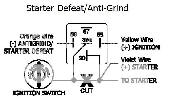 so the orange wire is from the brain
87a is the starter wire from the ignition switch
these are the next part i need verification from..
for pin 30 i know the other end of the starter cable going to the starter motor goes there, but the other one listed here is a violet wire. i believe they are talking about the starter output wire from the brain? so i just put them both on pin 30? this one i believe im correct based on a few searches here verifying that.
pin 85 is the one that is confusing me. its for the yellow ignition wire from the brain i believe. however on the brain i have 2
- the one from the starter harness
- the one from the main harness
the one from the starter harness is an output
the main harness one is listed as ignition INPUT (+) (must be connected) its described in the manual as: +12v ign input. wire must connect to a main ignition wire at the ignition harness. this wire must show +12v when ignition is on and while cranking the starter. the voltage must not drop when car is starting.
so i dont know there. if i connect the ign yellow wire from the starter harness on the brain, it doesnt seem logical. or since both of those wires need to connect to the ign wire at the ign switch, do i just run a T-tap from there to pin 85?
so the orange wire is from the brain
87a is the starter wire from the ignition switch
these are the next part i need verification from..
for pin 30 i know the other end of the starter cable going to the starter motor goes there, but the other one listed here is a violet wire. i believe they are talking about the starter output wire from the brain? so i just put them both on pin 30? this one i believe im correct based on a few searches here verifying that.
pin 85 is the one that is confusing me. its for the yellow ignition wire from the brain i believe. however on the brain i have 2
- the one from the starter harness
- the one from the main harness
the one from the starter harness is an output
the main harness one is listed as ignition INPUT (+) (must be connected) its described in the manual as: +12v ign input. wire must connect to a main ignition wire at the ignition harness. this wire must show +12v when ignition is on and while cranking the starter. the voltage must not drop when car is starting.
so i dont know there. if i connect the ign yellow wire from the starter harness on the brain, it doesnt seem logical. or since both of those wires need to connect to the ign wire at the ign switch, do i just run a T-tap from there to pin 85?

Posted: April 11, 2009 at 2:19 PM / IP Logged
Posted: April 11, 2009 at 2:21 PM / IP Logged
Posted: April 14, 2009 at 11:47 PM / IP Logged
Sorry, you can NOT post a reply.
This topic is closed.
 Printable version
| You cannot post new topics in this forum You cannot reply to topics in this forum You cannot delete your posts in this forum You cannot edit your posts in this forum You cannot create polls in this forum You cannot vote in polls in this forum |

| Search the12volt.com |
Follow the12volt.com 
Tuesday, May 5, 2026 • Copyright © 1999-2026 the12volt.com, All Rights Reserved • Privacy Policy & Use of Cookies

Tuesday, May 5, 2026 • Copyright © 1999-2026 the12volt.com, All Rights Reserved • Privacy Policy & Use of Cookies
Disclaimer:
*All information on this site ( the12volt.com ) is provided "as is" without any warranty of any kind, either expressed or implied, including but not limited to fitness for a particular use. Any user assumes the entire risk as to the accuracy and use of this information. Please
verify all wire colors and diagrams before applying any information.
