the12volt.com spacer
icon

04 dodge ram 1500


Post ReplyPost New Topic
< Prev Topic Next Topic >
cezarm 
Member - Posts: 18
Member spacespace
Joined: April 02, 2009
Location: California, United States
Posted: May 01, 2009 at 4:13 PM / IP Logged  

04 dodge ram 1500 -- posted image.need expertise input on gsm alarm hook up

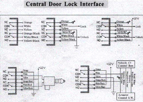
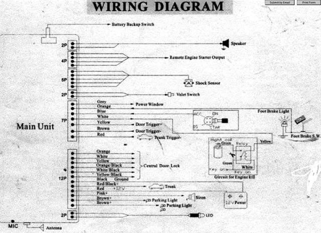
I am installing a gsm type alarm system with remote start ona 04 Dodge Ram 1500 Quad Cab. I would like to gain some knowledge particulaly on the remote start and starter interupt relay wiring. I have all the wiring info for the vehicle. I know where everything is located and I have chosen to go with the 820 & 330 Ohm resistors for the lock/unlock . We'll see if those will work, however on the 2nd ignition wire I read that this wire must be programmed to read neg. when in running position. I'm assuming this is the ignition wire that the remote start box hooks up to? I have attached these two drawings if this helps getting my questions answered. I removed a karr 4040A from the truck. I only pulled out 2 relays total. 1 for the starter kill and 1 for the parking lights. The resistors were hooked up inline from the alarm output to the PURPLE / dk. green  wire that controls the lock/unlock multi-plexed door lock system. I'm a little confused with this central door lock interface drawing. I am not even sure if this would apply considering the alarm I took off looked so simple but also wondering if that one was hooked up correctly? Every alarm manufacturer stresses to use relays and this karr alarm that came from the dealer didnt use any on the doors? Some assistance would be greatly appreciated. Thanks!04 dodge ram 1500 -- posted image.

skwearl 
Member - Posts: 20
Member spacespace
Joined: September 06, 2007
Location: British Columbia, Canada
Posted: May 01, 2009 at 7:25 PM / IP Logged  

Give me a call at work, 250-787-7900 to discuss these issues.

Ask for skwearl

howie ll 
Pot Metal - Posts: 16,466
Pot Metal spacespace
Joined: January 09, 2007
Location: United Kingdom
Posted: May 02, 2009 at 4:40 PM / IP Logged  
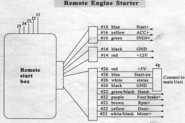
Your unit already has relay driven lock outputs, you don't need any.  Secondly I recognise that wiring diagramme, good luck making it work.  As a point where's the tach or alternator input wire to recognise engine start?  You will also need a factory immobiliser by-pass.
cezarm 
Member - Posts: 18
Member spacespace
Joined: April 02, 2009
Location: California, United States
Posted: May 02, 2009 at 7:10 PM / IP Logged  

04 dodge ram 1500 -- posted image.

Thanks for the info on the built in relays. You mentioned something about the Remote Start recognizing or not recognizing Tach or Alternator wire. I added an additional drawing specifying wires on the Remote Start Box.This will pretty much let you see what I have been supplied to work with. Would you be able to give me any suggestions on the Central Door Lock Interface Diagram? How would I achieve a correct install if I am wanting to go off the MultiPlexed Wires for my Door Locks and my parking lights/headlights along with the Dome Light Supervision. I apologize for the lack of knowledge I am demonstrating however, it is my 1st install04 dodge ram 1500 -- posted image.

howie ll 
Pot Metal - Posts: 16,466
Pot Metal spacespace
Joined: January 09, 2007
Location: United Kingdom
Posted: May 03, 2009 at 3:01 AM / IP Logged  
In your first post, look at the top middle diagramme, that's the one to use then feed each lock output to each resister as before. Make sure that the grounding wire goes to a good ground, preferably a chassis bolt.
cezarm 
Member - Posts: 18
Member spacespace
Joined: April 02, 2009
Location: California, United States
Posted: May 03, 2009 at 12:08 PM / IP Logged  
ok, got you on the Door Locks! Appreciate your input. Any suggestions on how to do the Starter kill/remote start wiring? Os it possible to use one relay to run parking lights/headlights and dome light supervision?
howie ll 
Pot Metal - Posts: 16,466
Pot Metal spacespace
Joined: January 09, 2007
Location: United Kingdom
Posted: May 03, 2009 at 1:57 PM / IP Logged  
No separate relays. Actually shouldn't need another relay for parking lights, your alarm light output should be relay driven, polarity selected by the input wire.  Assumi ng it has one, the brown are out put, if there is no way of giving them a neg (I believe it uses a neg feed thrpough a resistor, if pos don't worry) you might be able to select polarity via a jumper or dip switch.
cezarm 
Member - Posts: 18
Member spacespace
Joined: April 02, 2009
Location: California, United States
Posted: May 03, 2009 at 2:45 PM / IP Logged  
Howie, I have accessed the wires on my parking lights and headlights at the switch using the WHITE/ green wire with the resistor values given. These lights are through a neg, trigger. The (2) brown alarm outputs are + as the diagram shows, above. There is a dimmer for the interior lights that also turns your cargo light on/off next to the switch. Can any of these wires in this immediate area control your dome light supervision?
howie ll 
Pot Metal - Posts: 16,466
Pot Metal spacespace
Joined: January 09, 2007
Location: United Kingdom
Posted: May 03, 2009 at 5:25 PM / IP Logged  
Go to the vehicle wiring section and look  up yoyur vehicle, it tells you every thing. There are 2 pos inputs for the lights as well as the neg at the switch, but for the neg you will need a relay, brown from alarm to 86, good neg to 95 and 30 out resistor and switch. Dome light supervision is also mentioned BUT if your dome light comes on wheen the driver's door is unlocked rather than opened you wont need it.
cezarm 
Member - Posts: 18
Member spacespace
Joined: April 02, 2009
Location: California, United States
Posted: May 03, 2009 at 5:37 PM / IP Logged  
OK, I got you on that. Thanks again. I 'll have this puppy just about done today. Any suggestions on the remote start wiring? I know you mentioned the immobilizer. Is this part mandatory? Or it will not function correctly? I'm open to any input on this remote start...
Page of 2

  Printable version Printable version Post ReplyPost New Topic
You cannot post new topics in this forum
You cannot reply to topics in this forum
You cannot delete your posts in this forum
You cannot edit your posts in this forum
You cannot create polls in this forum
You cannot vote in polls in this forum

  •  
Search the12volt.com
Follow the12volt.com Follow the12volt.com on Facebook
Wednesday, April 24, 2024 • Copyright © 1999-2024 the12volt.com, All Rights Reserved Privacy Policy & Use of Cookies
Disclaimer: *All information on this site ( the12volt.com ) is provided "as is" without any warranty of any kind, either expressed or implied, including but not limited to fitness for a particular use. Any user assumes the entire risk as to the accuracy and use of this information. Please verify all wire colors and diagrams before applying any information.

Secured by Sectigo
the12volt.com spacer
Support the12volt.com
Top
the12volt.com spacer