the12volt.com spacer
icon

kicker kx 650.4


Post ReplyPost New Topic
< Prev Topic Next Topic >
terry osborn 
Copper - Posts: 54
Copper spaceThis member has made a donation to the12volt.com. Click here for more info.spacespace
Joined: May 16, 2009
Location: Texas, United States
Posted: June 06, 2009 at 4:13 PM / IP Logged  
Yes,i have checked the fuse and gone so far as to check for available 120v downstream to the transformer.Also checked for output on the secondary from the transformer.It seemed to be ok.
Story on this is: It has 2 voltage settings depending on the switch 13.2vdc and 14.4vdc.It was left in the 14.4 vdc to quick charge the battery and at some point the internal fan had come apart,and i would guestimate things got a bit hot.Considering that it was inside a closed cabinet,inside a closed up aluminum racecar trailer,in july,and in Texas.
I've noticed one thing about "Experts". When one shows up,someone gets hurt!
i am an idiot 
Platinum - Posts: 13,677
Platinum spaceThis member consistently provides reliable informationspace
Joined: September 21, 2006
Location: Louisiana, United States
Posted: June 07, 2009 at 7:00 AM / IP Logged  
What kind of AC voltage do you have on the secondary side of the transformer? Is the secondary of the transformer connected to the Diodes? The ones labeled D1 to D5.
terry osborn 
Copper - Posts: 54
Copper spaceThis member has made a donation to the12volt.com. Click here for more info.spacespace
Joined: May 16, 2009
Location: Texas, United States
Posted: June 07, 2009 at 9:37 AM / IP Logged  
I'm going to recheck the voltages on the transformer,primary and secondary I don't believe i got a positive reading on either in Vac.What seems odd is that i pick up Vdc downstream of the transformer,and the power on L.E.D is illuminated now.This was not the case before. The transformer appears to be a 16 pin multi-tap. What pins should i get readings on when checking the primary and secondary side. It's configured with 8 pins on primary and 8 on secondary,4 on left\4 on right.I work with large multitaps up to a million amps and jumper placements determine either buck or boost.However,i have a diagram for correct configuration and for this one i don't.
I've noticed one thing about "Experts". When one shows up,someone gets hurt!
i am an idiot 
Platinum - Posts: 13,677
Platinum spaceThis member consistently provides reliable informationspace
Joined: September 21, 2006
Location: Louisiana, United States
Posted: June 07, 2009 at 9:58 AM / IP Logged  

You will need to check from one leg to the other 7 and then check from leg 2 to the other 7.  Check all possible combinations and just let me know the highest voltage you come up with. 

The unit may be equipped with a thermal shut off device.  Was there anything mounted to the heat sink other than the FETs and the Diodes?

terry osborn 
Copper - Posts: 54
Copper spaceThis member has made a donation to the12volt.com. Click here for more info.spacespace
Joined: May 16, 2009
Location: Texas, United States
Posted: June 08, 2009 at 12:30 AM / IP Logged  
I rechecked the transformer and i'm not seeing any Vac on the primary or secondary.I traced the 120vac to find where it stops. It appears to end at a large 4 pin component which is clamped to the heatsink,on the opposite side of the mosfets.This component is the only thing that clamps to this side of the heatsink and it's close to the 120v supply plug.I'f you need a part# to identify it,i'll see what i can do.May have to remove it to get #.
I've noticed one thing about "Experts". When one shows up,someone gets hurt!
i am an idiot 
Platinum - Posts: 13,677
Platinum spaceThis member consistently provides reliable informationspace
Joined: September 21, 2006
Location: Louisiana, United States
Posted: June 08, 2009 at 6:13 AM / IP Logged  
Do not take it out, take a picture.  Is it a rectangular device with 3 right angle corners and one corner is 45'd twice?  If so, it is  a full wave bridge rectifier.  It converts AC to DC voltage.  The 2 legs that do not go to the transformer should have DC voltage on them.  Black lead on one leg red lead on the other. 
terry osborn 
Copper - Posts: 54
Copper spaceThis member has made a donation to the12volt.com. Click here for more info.spacespace
Joined: May 16, 2009
Location: Texas, United States
Posted: June 08, 2009 at 10:36 PM / IP Logged  
Ok, let's see if can deliver correct answers to several pending questions.There is no Vac present on the primary or secondary of the transformer.Yes,the 4 diodes labeled D1 thru D5 are connected to the transformer.Your description of the component in question sounds exactly like what i see. I have 120vac present between 2 legs of the rectifier.The only DC voltage i see at the rectifier is millivolts.I'm sending pictures to your E-mail for review.
I've noticed one thing about "Experts". When one shows up,someone gets hurt!
i am an idiot 
Platinum - Posts: 13,677
Platinum spaceThis member consistently provides reliable informationspace
Joined: September 21, 2006
Location: Louisiana, United States
Posted: June 08, 2009 at 10:43 PM / IP Logged  
Unplug the unit and check the 4 legged device. It is basically 4 diodes in one case. Black lead on one of the legs that has the AC voltage, red lead to one of the others. Then the other. Reverse leads and check again. I have no pictures yet. gonna keep looking.
haemphyst 
Platinum - Posts: 5,054
Platinum spaceThis member has been recognized as an authority in Electrical Theory. Click here for more info.spaceThis member has been recognized as an authority in Mobile Audio and Video. Click here for more info.spacespace
Joined: January 19, 2003
Location: Michigan, Bouvet Island
Posted: June 09, 2009 at 7:39 AM / IP Logged  
:::::THREAD HIJACK!!!::::: kicker kx 650.4 - Page 5 -- posted image.
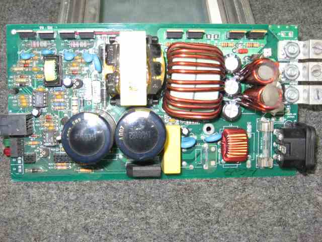
The bridge can't be connected to the primary side of the transformer. That is indeed the low voltage side of the circuit. Also, your description of millivolts on the DC legs of the bridge sounds to me like an open bridge. I think that's your defective component...
If there is no voltage present at the primary side of the transformer, (is that the case, or did I misread somewhere?) I expect there might be a thermal fuse gone off somewhere. They are commonly shaped like a small bullet, with a resin "nosecone" and a metal tube body, and the ends attached to relatively heavy gauge leads.
Picture one... (These are the most common, in household, low-current devices like your power supply.)
Picture two...
They are sometimes buried inside the transformer, and if you don't see one, this may be the case.
One additional test, if I may suggest: Unplug the power supply. Turn power switch to the "on" position. Test for continuity between the two prongs of the AC plug. Is it a three prong plug? If so, also check for continuity between the ground prong, and the other two (hot and neutral) prongs, in both on and off power switch positions. Post back here, and let me know what you find. If there is no continuity, then your failure is MOST likely on the primary side of this paticular power supply, and best bet is the thermal fuse, unless there was an over-current condition as well as the thermal condition...
As the input side has to have AC to work, the polarity of your meter jumpers won't matter, but only in this case.
Is there a part number or model number on the transformer itself?
It all reminds me of something that Molière once said to Guy de Maupassant at a café in Vienna: "That's nice. You should write it down."
i am an idiot 
Platinum - Posts: 13,677
Platinum spaceThis member consistently provides reliable informationspace
Joined: September 21, 2006
Location: Louisiana, United States
Posted: June 09, 2009 at 8:37 AM / IP Logged  

Not that kind of supply.  This appears to be some new fangled device that has no transformer like we both were thinking.  It appears as though they rectify the 110 and built a DC to DC supply to step it down to 13.8.    I too am suspecting a bad bridge.  He is checking that for his next post. 

kicker kx 650.4 - Page 5 -- posted image.

Page of 8

  Printable version Printable version Post ReplyPost New Topic
You cannot post new topics in this forum
You cannot reply to topics in this forum
You cannot delete your posts in this forum
You cannot edit your posts in this forum
You cannot create polls in this forum
You cannot vote in polls in this forum

  •  
Search the12volt.com
Follow the12volt.com Follow the12volt.com on Facebook
Monday, June 10, 2024 • Copyright © 1999-2024 the12volt.com, All Rights Reserved Privacy Policy & Use of Cookies
Disclaimer: *All information on this site ( the12volt.com ) is provided "as is" without any warranty of any kind, either expressed or implied, including but not limited to fitness for a particular use. Any user assumes the entire risk as to the accuracy and use of this information. Please verify all wire colors and diagrams before applying any information.

Secured by Sectigo
the12volt.com spacer
Support the12volt.com
Top
the12volt.com spacer