


Sony 16 Pin Diagram


Posted: May 16, 2009 at 7:13 PM / IP Logged


Posted: May 16, 2009 at 7:40 PM / IP Logged
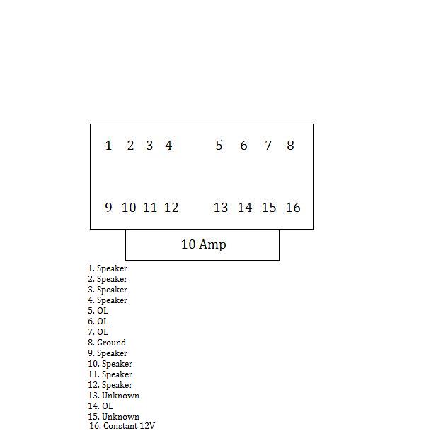
 Attach the black lead of the meter to the chassis of the radio. Now touch the red lead to each of the pins on the plug. One pin will beep at you and read very near 0.000. Label that pin as ground. There will be 8 pins that have the same exact reading. Those are speaker wires. We will get to that later. If there is a fuse, you should be able to get a meter lead on the element of the fuse, there is a hole on each side of the fuse that allows access to the element. One lead on the fuse other lead to the remaining unidentified pins, one of them will read very near 0.000 label that one as constant voltage. You should have only 2 or 3 unidentified pins now. Draw a picture of what you found or take a pic and label what you have found, I can tell you where the switched wire is located.
Posted: May 18, 2009 at 12:23 AM / IP Logged
Posted: May 18, 2009 at 1:37 AM / IP Logged
Posted: May 18, 2009 at 4:52 PM / IP Logged
Posted: May 18, 2009 at 5:58 PM / IP Logged
Sorry, you can NOT post a reply.
This topic is closed.
 Printable version
| You cannot post new topics in this forum You cannot reply to topics in this forum You cannot delete your posts in this forum You cannot edit your posts in this forum You cannot create polls in this forum You cannot vote in polls in this forum |

| Search the12volt.com |
Follow the12volt.com 
Sunday, May 5, 2024 • Copyright © 1999-2024 the12volt.com, All Rights Reserved • Privacy Policy & Use of Cookies

Sunday, May 5, 2024 • Copyright © 1999-2024 the12volt.com, All Rights Reserved • Privacy Policy & Use of Cookies
Disclaimer:
*All information on this site ( the12volt.com ) is provided "as is" without any warranty of any kind, either expressed or implied, including but not limited to fitness for a particular use. Any user assumes the entire risk as to the accuracy and use of this information. Please
verify all wire colors and diagrams before applying any information.
