the12volt.com spacer
icon

Adding a Second Battery


Post ReplyPost New Topic
< Prev Topic Next Topic >
salden77 
Member - Posts: 11
Member spacespace
Joined: November 19, 2009
Location: New York, United States
Posted: November 26, 2009 at 11:24 AM / IP Logged  
i have a 2006 gmc sierra, 4.8 liter, just installed dual optima batterys, if your truck didnt come with plow prep. package you will need to buy an aux battery tray, battery hold down, bolts on the right side next to firewall which i can give you all the part numbers if you need. i went battery to battery, no isolator, the best wire to use is welding cable, i used #2 awg. if you have any questions or need pictures let me know and ill hook you up.
salden77
oldspark 
Gold - Posts: 4,913
Gold spacespace
Joined: November 03, 2008
Location: Australia
Posted: November 26, 2009 at 11:52 PM / IP Logged  
I use an ordinary relay instead of complex equipment.
The 150A relay cost AUD$15.
It connects the aux battery whenever the vehicle is charging.
I have a $7 50A circuit breakers at each end.   
I also have a $25 under-voltage 80A latching cutout from the aux battery to its loads.
I was using the same circuit (adjusted for 13.5V) for the charge-sense connection until I replaced it with the relay.
Normally I'd just use a 30A setup, but a manual switch allows paralleling of my weaker front battery during extreme cranking (CB upgrade pending if required).
jimmy poulin 
Member - Posts: 4
Member spacespace
Joined: November 28, 2009
Location: Quebec, Canada
Posted: November 28, 2009 at 4:55 PM / IP Logged  
Hi!
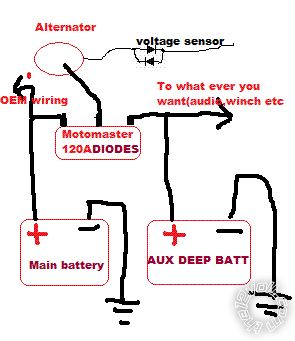
Simply use low cost schottky diode in line with the alternator, battery or line you want to isolate. Go look on eBay, digikey or other electronic store. They go from 400A to 0.0001A in a wild variety of voltage and price. You also can stalk them in parallel for more amp. The voltage drop is 0.3-1 volt but typically 0.7. If this lost is too much for you or you want a sightly higher voltage and a easily confuse with electronic. On GM, put normal diode parallel side up to side down on the voltage sense wire. and you have almost 1 volt more!!!-=-
oldspark 
Gold - Posts: 4,913
Gold spacespace
Joined: November 03, 2008
Location: Australia
Posted: November 28, 2009 at 6:19 PM / IP Logged  
A Schottky isn't required for its speed in an auto system - an ordinary diode will do.
But if Schottkys have lower voltage drop and Germaniums aren't obtainable, the fine.
But a diode will not prevent the original battery discharging into the second if the second fails.
And the second is likely to fail if constantly subject to a lower charge voltage than the first (ie, via a diode).
I recommend the relay option above. A cheap 15A or 30A relay should be fine for smaller batteries (I have used them for car batteries).   
If the batteries are adjacent to each other, fuses/breakers are not required - except to protect the relay.
It only connects the batteries whilst charging.
The same relay else other battery interconnection can be used to parallel the batteries if required (ie, for cranking),
Parallel batteries should be avoided.
Keep in mind that a parallel battery halves the battery's reliability.
PS - tweaking the "sense" wire works for most alternators except the D+ only types (AFAIK).
Sense-wire boosters and other circuits are used by Rally drivers & audio buffs for maximum system voltage hence maximum headlamp brightness, audio power etc. (Once even maximum spark before CDIs!)
Typically they would raise the system voltage to 14.4V at the battery where 14.4 was the common max battery charge voltage; higher where battery life was not as important.   
It is the same reason many cook their batteries. If the sense wire is lower than the battery voltage due to intermediate loads (lights, wipers, brakes etc), the regulator will boot output an equivalent amount. A voltage drop of 1.5V can mean 15.9V at the battery - hence overcharging and possibly damaging other loads. (Hence why special care is needed with most two-wire systems - ie IGN & charge Lamp aka Ig or S & L etc.)
jimmy poulin 
Member - Posts: 4
Member spacespace
Joined: November 28, 2009
Location: Quebec, Canada
Posted: November 28, 2009 at 8:30 PM / IP Logged  
Adding a Second Battery - Page 2 -- posted image.
oldspark 
Gold - Posts: 4,913
Gold spacespace
Joined: November 03, 2008
Location: Australia
Posted: November 28, 2009 at 11:48 PM / IP Logged  
That's fine if you don't mind the independent and hence unequal discharge rates from the batteries and hence no load sharing.
And any loads off the alternator handle the extra voltage (ie, as per Rally setups.)
I was assuming a standard load/battery sharing arrangement whilst charging with equal system voltage.
How does the dual diode cost compare to a relay (which I estimate to be $15 for 150A).
And what about heatsinking requirements - are the diodes easy to isolate from the heatsink?
katman 
Member - Posts: 15
Member spacespace
Joined: September 24, 2009
Posted: November 29, 2009 at 3:08 AM / IP Logged  

IÍ wanted to find a high amperage LATCHING RELAY.  Where did you find one

and what did it cost?  Wanted to keep my HID lighting ballasts off when I

start the engine then bring them on to avoid problems with them.

oldspark wrote:
I use an ordinary relay instead of complex equipment.
The 150A relay cost AUD$15.
It connects the aux battery whenever the vehicle is charging.
I have a $7 50A circuit breakers at each end.   
I also have a $25 under-voltage 80A latching cutout from the aux battery to its loads.
I was using the same circuit (adjusted for 13.5V) for the charge-sense connection until I replaced it with the relay.
Normally I'd just use a 30A setup, but a manual switch allows paralleling of my weaker front battery during extreme cranking (CB upgrade pending if required).

"All paid jobs absorb and degrade the mind."
Aristotle
katman 
Member - Posts: 15
Member spacespace
Joined: September 24, 2009
Posted: November 29, 2009 at 3:21 AM / IP Logged  

Forgot to mention I have a Honda bike.  It has a 400 watt alternator @ 5,000 rpm.  Puts out 15.2 volts at peak output.  This is good with the PC-680 Odyssey as the sencing relay and associated wiring drops the voltage a bit. The PC-680 needs at least 14.2 volts to reach saturation and 13.8 as a trickle charge.  They can take a  lot of amperage on charge but needs the higher voltage to reach full charge.  I find  it's better to connect my wall charger (from Odyssey) directly to the AUX. battery and let it feed back through to the main battery.  Otherwise the voltage drop through the Voltage Sencing Relay drops it below the voltage to fully charge the AUX. battery.

My main battery is also a sealed battery so it takes a higher voltage to charge it FULLY.  It's a rather small battery and sits in the heat above the engine.  In winter that's okay but during summer heat I plan on moving it out of the OEM spot.  It hasn't failed in 25,000 miles and 4 years of use.  Had the AUX battery in place about 2 years now.

Í can't tell which lead is the B+ from the alternator by the schematics in the manual.  I THINK it's a larger red wire to the main fuse.  Going to measure it to see what's coming to it. The schematic is not marked for the B+ and my local dealer doesn't know (HUH? You'd think they'd know this for diagnostics?  Any help is appreciated.

"All paid jobs absorb and degrade the mind."
Aristotle
oldspark 
Gold - Posts: 4,913
Gold spacespace
Joined: November 03, 2008
Location: Australia
Posted: November 29, 2009 at 7:58 AM / IP Logged  
Latching relays do exist - the under/over voltage circuit I use has an 80A mechanical latching relay so that no power is consumed other than when changing state.   
However I use standard relays with whatever circuit or connections are required.
EG - I have a pump system that terns on at level-1 and off at level-2.
It is 2 fluid level switches and 1 standard relay (SPST aka on-off), though I also use 2 diodes to ensure the switches never carry the load current.
I'll have to re-read above to see what was is required in your case.
And is it Odyssey that reckon no current limit applies and that you can exceed 14.4V (up to 15.6V from memory) PROVIDED some battery temperature is not exceeded? (Or was it Optima?)
Normally AGM batteries are a constant voltage charge (say 14.4V) but with a current limit (20% of C10 or whatever....).
I find it strange that a "lead acid" AGM would allow above 14.4V (at 25 degC which is normally considered the voltage for major gassing onset).
Also strange that a battery would allow any charge current.
Temperature increase is a indication of overcharging - it is not the preferred method of determining full or over charge etc - rather, it is an alarm situation (ie, stop charging!).
How long does it take the internal heat to reach the outer casing?
And if the casing is in a very cold environment, will this cool the casing hence masking high internal temperatures?   
(For wet lead acids and semi-sealed - fine - you can insert a probe; but not AGMs.)
Not that I care - I don't pay their warranty claims, and I don't have to prove to them that I never exceeded their specified temperature ('cos I don't use them).
BTW - lead-acid batteries are usually charged at 14.4V (2.4V/cell).
When full, they are usually reduced to a float voltage of 13.8V (2.3V/cell).
katman 
Member - Posts: 15
Member spacespace
Joined: September 24, 2009
Posted: November 29, 2009 at 8:44 AM / IP Logged  

This pdf. file gives specs for charging the Odyssey batteries can be seen at the following site:

http://www.odysseybattery.com/documents/US-ODY-OM-007_0209_rev_000.pdf

Where did you find the 80 amp latching relay?

"All paid jobs absorb and degrade the mind."
Aristotle
Page of 5

  Printable version Printable version Post ReplyPost New Topic
You cannot post new topics in this forum
You cannot reply to topics in this forum
You cannot delete your posts in this forum
You cannot edit your posts in this forum
You cannot create polls in this forum
You cannot vote in polls in this forum

  •  
Search the12volt.com
Follow the12volt.com Follow the12volt.com on Facebook
Saturday, April 27, 2024 • Copyright © 1999-2024 the12volt.com, All Rights Reserved Privacy Policy & Use of Cookies
Disclaimer: *All information on this site ( the12volt.com ) is provided "as is" without any warranty of any kind, either expressed or implied, including but not limited to fitness for a particular use. Any user assumes the entire risk as to the accuracy and use of this information. Please verify all wire colors and diagrams before applying any information.

Secured by Sectigo
the12volt.com spacer
Support the12volt.com
Top
the12volt.com spacer