the12volt.com spacer
icon

Adding a Second Battery


Post ReplyPost New Topic
< Prev Topic Next Topic >
oldspark 
Gold - Posts: 4,913
Gold spacespace
Joined: November 03, 2008
Location: Australia
Posted: November 29, 2009 at 10:27 AM / IP Logged  
Thanks.
It was Optima - they state for Rapid Recharge: (Constant voltage charger) - Maximum voltage 15.6 volts. No current limit as long as battery temperature remains below 125F (51.7C). Charge until current drops below 1 amp.
I like the Odyssey warranty - void if "Overcharging, undercharging..." and the charge rate shall be a "minimum of 40% of the battery's 10-hour rating" and eg, a minimum of 40 amps for a 31-PC2150 battery that is routinely discharged deeply (expensive charger!)
Latching relay - see http://secure.oatleyelectronics.com//product_info.php?products_id=522 (AUD $6.50).
It's used in the over/under voltage sensor I mentioned - http://secure.oatleyelectronics.com//product_info.php?products_id=270 (AUD$22.00, kit K227) as well as other products like K231B pictured below (Remote Control Receiver Kit with dual 80Amp Relays).
Oatley have some great kits, and cheap components (power FETs etc).
Adding a Second Battery - Page 3 -- posted image.
jimmy poulin 
Member - Posts: 4
Member spacespace
Joined: November 28, 2009
Location: Quebec, Canada
Posted: November 29, 2009 at 7:28 PM / IP Logged  
Of COURSE! Do never do or exceed 15 volt on car to avoid damage to electronic and battery. But the voltage to battery and everywhere in my car was 13.4 to 13.7. Much Too low! In winter, the battery doesn't fully charge and freeze up below 0°F. with a 500 Omn pot and the diode trick between i set it to 14.3 - 14.6. (But the pot for me be end to no use, because set over the max of the diode.) So, no frying battery, just use the diode to set the Max adjust voltage drop to alternator for safety! And now the same battery hold easily a good charge below down to minus 25°F. Do always check the voltage on different circuits on the car, specially at the battery for low/high voltage!
katman 
Member - Posts: 15
Member spacespace
Joined: September 24, 2009
Posted: November 29, 2009 at 8:22 PM / IP Logged  

Old Spark, was hoping for a simple momentary switch operation.  I notice these units need UHF transmitters, etc.  Is there a way to use two momentary push buttons to select relays?  Or just have to push one button to  bring on the relay after poweing down the ignition switch and turning it back on?

Jim Poulin, Going to have to read the section on boosting the voltage if needed in certain vehicles.  Thanks for the input though.  Going to do some more reading.

Thanks for any input it's a steep learning curve for me.

"All paid jobs absorb and degrade the mind."
Aristotle
oldspark 
Gold - Posts: 4,913
Gold spacespace
Joined: November 03, 2008
Location: Australia
Posted: November 29, 2009 at 10:42 PM / IP Logged  
katman wrote:
I notice these units need UHF transmitters
Only because it is a remote control which has nothing to do with this subject - I only posted that pic to show what the latching relay looked like (since there was no pic for the relay itself).
Here's a pic of it in the under/overvoltage sensor I often refer to:
( With thanks to Oatley Electronics - see oatleyelectronics.com products_id=270 )
Adding a Second Battery - Page 3 -- posted image.
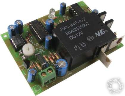
(Ha! Not only is this kit & circuit probably the best I have seen - and much cheaper than alternatives - the kit itself is almost cheaper than an 80A relay. (Ok... maybe double, but hopefully you know what I mean.) But be aware this picture is the kit AFTER you construct it, and no enclosure is included.)
You could use a push button to toggle the Oatley latching relay. I'm not sure if it would need some contact de-bounce (RC filter etc).
But, you'd have to devise some way of knowing which position it's in, and to place it in the desired state when shut off.
The Oatley under/over-voltage (aka Dual Battery) kit K227 does all that automatically and will turn the relay off if power is disconnected.
Although I initially ran the Oatley K227 up front to connect my aux battery, I later changed to the charge-lamp circuit. (In part so I could manually reconnect for jump starting; in part because I never quite finished its enclosure before pressure cleaning the engine bay. The rear "low voltage disconnect" K227 was housed in an IP65 or similar enclosure.)
This morning I posted a similar type of implementation in using relays for auto on solutions (page 2). See if that helps.
[TIP - images with too-long filnemes will not post!]
And Jimmy is correct with his comments etc.
Remember that a vehicle's charging system is designed as a constant-voltage system to charge and maintain a battery. Hence why their settings may vary from a float voltage of 13.8V to the max long-term charging voltage of 14.4V.
Most automotive 12V equipment is rated at 13.8V (for power consumption etc) but is (or should be!!) designed to handle a reasonable time at 16V.
Exceeding 16V can cause damage. (Spikes etc may be over 200V, but they are of short duration and are a separate consideration.)
But in essence, as long as the battery gets its required voltage range (13.8 to 14.4V), and the load is within its limits, anything goes.
Hence the different techniques such as running driving lights etc direct from a higher than 14.4V alternator output whilst limiting the battery to 14.4V. (Eg, maybe dropping diodes or resistors, or the wiring & fuse losses from the alternator to the battery. In old days they used ammeters but they have now been recognised for being as useless as they were then too.)
I did mention somewhere recently of diode and variable-resistor circuits in the alternator (regulator's) sense line to boost the alternator's output voltage. (Maybe earlier in here?)
The charging voltages etc for batteries should vary with their temperature. Cars etc are usually not such a problem because batteries will be at higher temps (engine bay or boot).
But trucks & motorbikes may have exposed batteries. I'd suspect snow machines to have their batteries enclosed and close to the engine.
Fussy systems have temp sensors on their batteries and adjust the charge to suit.
Many alternators have internal temp sensors - they assume the battery is at a similar temperature. (Alternators may also have charging profiles like starting with 14.4V or higher and then dropping to 13.8 once charged.)   
And of course we all know that once the battery is charged, there is no battery current flow (excluding instantaneous load changes, and the battery's normal "float current").
two12 
Copper - Posts: 84
Copper spacespace
Joined: November 24, 2009
Posted: December 15, 2009 at 9:17 PM / IP Logged  
Split Charge Diodes are dated and do not work properly! http://www.smartgauge.co.uk/diodes.html
so they say..
heres a couple of different types of systems:
http://www.smartgauge.co.uk/smartbank.html
http://www.powerstream.com/battery-isolator.htm
Im still undecided as to whats the best way but my set up is a bit more complicated with more than two batteries and more than two charge sources.
just thought I would add those on-topic links but youll have to cut and paste them as I dont have javascripting enabled and this forum requires it for hotlinking.
I like oldsparks suggestion for a standard two battery system.
katman wrote:

I made a dual battery charging system for my motorcycles and scooters so I never have to worry about the start battery failing due to accessory power draw. I use the Odessey PC-680 (AGM Type Battery) as the aux. or House battery. Used a system designed for boating from BEP Marine that incorporates three switches and a VOLTAGE SENCING RELAY to charge the Aux. / House battery when the alternator is putting out 13.8 volts or better. That way my start battery is always charged up first.

I mounted the battery and charging system in a UM-1 size battery box commonly used in trolling motor applications for fishing boats. Used a quick disconnect plug (50 amp) between the start battery and the dual battery charging system in the battery box so I can move it between my vehicles. I'm making a fuse box that incorporates quick disconnect harness from DEL CITY ELECTRIC SUPPLY (toll free: 800-654-4757) which has 3 ea 12ga wires and 5 ea. 16 ga. wires. A harness with matching quick disconnect plug delivers fused circuits to the front and another one delivers fused power to the rear of the bikes and scooters.

The Odessey PC 680 is a dual purpose battery (deep cycle and starting) that will turn over an eight cyl. engine. The control switches have a series parallel switch that will help start the engine using both batteries in an emergency. There is a switch for each of the batteries. On most vehicles you wire the dual charging system using the output of the charging system so the START battery switch must remain ON. The Aux. / House battery power can control all your accessories with the House Battery Switch. The dual battery charging system runs about $150 on line the Odessey PC-680 runs about $110 delivered. I photocopied the instructions and laminated them to keep a copy in the battery box JUST in case.

I am an experienced electrician so the design and installation work wasn't to bad. The average guy could have a difficult time making a system like this work. The box is mounted to the floor of my scooters (have 3 of the same scooter which have 400 watt alternators in it's 250 c.c. engine.)

hey katman! any photos of your set-up? are you using a big car battery on a bike? I have a couple of multisport Hondas that I'd like to have extra power onboard. got anymore info?
thanks
oldspark 
Gold - Posts: 4,913
Gold spacespace
Joined: November 03, 2008
Location: Australia
Posted: December 15, 2009 at 10:04 PM / IP Logged  
And since I finally posted a diagram for a charging second battery using my aforementioned method, here is the link to the thread started my some clever dude.....    trailor alarm wiring
katman 
Member - Posts: 15
Member spacespace
Joined: September 24, 2009
Posted: December 15, 2009 at 10:05 PM / IP Logged  

I'll try to locate the photos.  It's an Odyssey PC-680 battery inside of a UM-1 battery box (trolling motor size battery for a fishing boat) the dual battery charging system by BEP is  mounted inside the box also.  The handles of the switches poke through the side of the box.  I have a fuse block by Blue Sea on the top of the box.  The main battery is connected through a 50 amp quick disconnect. 

Since I have three scooters I made the system transferable between them.  Plan on getting a used Honda Element or Scion Xb some day.  Will make it compatibale also.  I can run aux. lighting and audio equipment from the aux. battery.  That way my start battery is always charged full.  Also in the plan is a capacitor big enough to fire up the HID ballasts in the aux. lighting system.  That's why I wanted to incorporate a latching relay for when I shut down engine and restart after firing it back up.

"All paid jobs absorb and degrade the mind."
Aristotle
katman 
Member - Posts: 15
Member spacespace
Joined: September 24, 2009
Posted: December 15, 2009 at 10:17 PM / IP Logged  

I have to figure which wire is the B+ from the alternator on my Honda PS-250 scooter.  The schematic is not that clear which one actually charges the battery.  It shows the + battery lead as a start cable not the B+. 

Any comments appreciated.

oldspark wrote:
And since I finally posted a diagram for a charging second battery using my aforementioned method, here is the link to the thread started my some clever dude.....    trailor alarm wiring

"All paid jobs absorb and degrade the mind."
Aristotle
berzina123 
Member - Posts: 5
Member spacespace
Joined: December 16, 2009
Location: Manitoba, Aruba
Posted: December 16, 2009 at 1:08 AM / IP Logged  
If both batteries are the same you can get by without an isolator, but if not .an isolator is your best bet, plus if the plow battery happens to get discharged without the truck running, the other battery will still have starting power. i would run at least 4 guage wire to do all this too .. and replace the charging wire off the alternator with 4 guage also
oldspark 
Gold - Posts: 4,913
Gold spacespace
Joined: November 03, 2008
Location: Australia
Posted: December 16, 2009 at 3:45 AM / IP Logged  
Katman, is that scooter the 400W system - ie, about 30A max output?
If the alternator is a rotor controlled unit, then there should only be one thick output wire. (Up to maybe 12G - 14G cable (40A - 30A).)
If it's a permanent magnet, aka "stator" system (thanks for the education BigTime77) as used on many marine motors, my 1972 Ducati and other simple/primitive machines, it may have a 2-phase output or split outputs - eg, one for "non critical" lights, the other for battery else ignition etc.
But the system you described earlier that senses charging (ie, above 13V or 13.5V etc) is the substitute for an alternator-regulator's D+ or L charge lamp output. (This is what BigTime77 would have to use for his marine outboard - there is no charge lamp nor regulator per se.)
The K227 voltage sensor I pictured above from Oatley Electronics does the same (see oatleyelectronics.com products_id=270).
The K227 uses an 80A latching relay. (Be aware that it is a kit - you have to assemble it.)
My wiring in trailor alarm wiring uses a charge lamp circuit. But that Aux-battery relay could instead be connected to the output of the K227 (latching relay) or any other "charge sensing" circuit. (Over-voltage switches can be made with an OPAmp, or a Zenor diode and transitor etc, probably even a Zenor and an optic switch.)
As Berzina suggested, an isolation switch is best. Having two paralleled batteries is useless if the second battery is to guard against a flat first.
But all this trouble for a scooter?
I used to push-start my GPz900 and GT750 when they were dead (not that the Duc GT750 had a starter motor, but it was harder to push start - the rear wheel would usually lock up!)
Then there was always the "flick rear wheel in center-stand" option, but that was only used with its essential "get hands out of spokes quickly" if the tyre couldn't be used.
(And finally the "fitter girlfriend" option. But these days I'm more realistic.)
BTW - other than getting too hot, the actual wire gauge from the charger may not be that important depending on where the voltage is sensed, and what limits the charger's output power.
The alternator/stator may put out 17.4V with a 3V cable drop to yield 14.4V at the battery. In many system, so what? Big deal!
(This is more obvious in permanent magnet systems where the excess voltage is shunted before the battery & loads.) 
Page of 5

  Printable version Printable version Post ReplyPost New Topic
You cannot post new topics in this forum
You cannot reply to topics in this forum
You cannot delete your posts in this forum
You cannot edit your posts in this forum
You cannot create polls in this forum
You cannot vote in polls in this forum

  •  
Search the12volt.com
Follow the12volt.com Follow the12volt.com on Facebook
Saturday, April 27, 2024 • Copyright © 1999-2024 the12volt.com, All Rights Reserved Privacy Policy & Use of Cookies
Disclaimer: *All information on this site ( the12volt.com ) is provided "as is" without any warranty of any kind, either expressed or implied, including but not limited to fitness for a particular use. Any user assumes the entire risk as to the accuracy and use of this information. Please verify all wire colors and diagrams before applying any information.

Secured by Sectigo
the12volt.com spacer
Support the12volt.com
Top
the12volt.com spacer