the12volt.com spacer
icon

How To Wire Viper 211hv? 96 Chevy Silverado


Post ReplyPost New Topic
< Prev Topic Next Topic >
nolangage 
Member - Posts: 6
Member spacespace
Joined: July 20, 2009
Location: Kansas, United States
Posted: July 20, 2009 at 5:33 PM / IP Logged  

I have a Viper 211 HV car alarm. and I can not figue out how to hook up the lock and unlock any help will be help full.  I am installing it on a 96 Chevy Silverado  1500 Extended Cab 3 Doors.  

thanks in advance.

PowerUp
ajstetler 
Copper - Posts: 94
Copper spacespace
Joined: October 31, 2008
Location: Illinois, United States
Posted: July 20, 2009 at 5:57 PM / IP Logged  
It's not an alarm, it's keyless entry only. Here is what you need to know...
FULL SIZE PICKUP       1996 -1997
KEY       T-HARNESS       IMMOBILIZER
N/A       GM-1       N/A
PART       COLOR       LOCATION       DIAGRAM
12 VOLT CONSTANT       RED (+)       IGNITION SWITCH HARNESS      
STARTER       PURPLE or YELLOW (+)       IGNITION SWITCH HARNESS      
STARTER 2       N/A            
IGNITION 1       PINK (+)       IGNITION SWITCH HARNESS      
IGNITION 2       PINK/WHITE (+) or WHITE (+) See NOTE *4       IGNITION SWITCH HARNESS      
IGNITION 3       N/A            
ACCESSORY /HEATER BLOWER 1       ORANGE (+)       IGNITION SWITCH HARNESS      
ACCESSORY /HEATER BLOWER 2       N/A            
KEYSENSE       N/A            
PARKING LIGHTS ( - )       N/A            
PARKING LIGHTS ( + )       BROWN (+)       @ HEADLIGHT SWITCH or FUSE PANEL      
POWER LOCK       LIGHT BLUE (TYPE C) See NOTE *1       IN DRIVERS DOOR HARNESS      
POWER UNLOCK       WHITE (TYPE C) See NOTE *1       IN DRIVERS DOOR HARNESS      
LOCK MOTOR WIRE       GRAY (+)       IN DRIVERS KICK PANEL, at DOOR HARNESS      
DOOR TRIGGER       PURPLE (-)       @ HEADLIGHT SWITCH      
DOMELIGHT SUPERVISION       USE DOOR TRIGGER, Requires #775 Relay            
TRUNK RELEASE       N/A            
SLIDING POWER DOOR       N/A            
HORN       BLACK (-)       @ STEERING COLUMN HARNESS      
TACH       WHITE       @ ECM See NOTE *2      
WAIT TO START LIGHT       See NOTE *3            
BRAKE       WHITE (+)       @ SWITCH ABOVE BRAKE PEDAL      
FACTORY ALARM DISARM       N/A            
ANTI-THEFT       N/A            
NOTES
NOTE *1 vehicles that are 2-Door are a TYPE C Door locking system and vehicles that are 4-Door are a TYPE A Door locking system.
NOTE *2 The ECM (Engine Control Module) is located on the Drivers Side Inner Fenderwell, with 2 plugs, the WHITE wire is in a plug marked "WHITE"
The TACH wire on the 6.5L DIESEL is a WHITE at the instrunemt cluster
NOTE *3 when hooking up a REMOTE STARTER on a DIESEL, if the WAIT to START wire from the Remote Starter does not wait until the Light on the dash turn out before cranking, you will need to program in the 5,10 or 15 Second WAIT to START TIMMER in the Installation Manual. On some vehicles the Wait to Start Light on the dash is not a true (+)Positive or (-)Negative and the wire from the Remote Starter will not owrk. When this Wait to Start Timmer is programmed, disconnect and tape up the Wait to Start wire from the Remote Starter that is tied into the Wait to Start Light on the dash.
NOTE *4 IMPORTANT !!!!! this wire MUST BE CONNECTED as IGNITION #2 for REMOTE STARTING!!!!!!
Big Al
nolangage 
Member - Posts: 6
Member spacespace
Joined: July 20, 2009
Location: Kansas, United States
Posted: July 20, 2009 at 6:12 PM / IP Logged  

Thanks for the reply back but when ever I hook the lock and unlock up nothing happens.  Seems you had the vech details with i also have took me a week to find them on line.  Can you tell me with viper wires to hook to which vehicle wires. 

Thanks in advace again.

PowerUp
t&t tech 
Platinum - Posts: 2,608
Platinum spacespace
Joined: October 05, 2008
Location: Trinidad and Tobago
Posted: July 20, 2009 at 8:12 PM / IP Logged  
i have never worked on your specific vehicle, but, the schematics above state that you have a type c locking system, which is direct wired reversing polarity switching, i have never used that specific model you're using either so i don't know if there are bult in relays in your unit, can you verify this?
commit your way to jehovah and he will act in your behalf. psalms 37:5
t&t tech 
Platinum - Posts: 2,608
Platinum spacespace
Joined: October 05, 2008
Location: Trinidad and Tobago
Posted: July 20, 2009 at 8:17 PM / IP Logged  
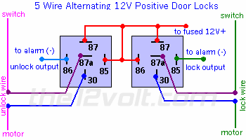
How To Wire Viper 211hv? 96 Chevy Silverado -- posted image.
commit your way to jehovah and he will act in your behalf. psalms 37:5
t&t tech 
Platinum - Posts: 2,608
Platinum spacespace
Joined: October 05, 2008
Location: Trinidad and Tobago
Posted: July 20, 2009 at 8:20 PM / IP Logged  
there is the diagram you need, i noticed you said three door, but the wiring diagram only makes mention of 2 doors or 4 doors, i am assuming here that you are counting the rear door also, so i posted the two door diagram. cheers.
commit your way to jehovah and he will act in your behalf. psalms 37:5
nolangage 
Member - Posts: 6
Member spacespace
Joined: July 20, 2009
Location: Kansas, United States
Posted: July 20, 2009 at 10:20 PM / IP Logged  

Thanks for all the help so far, How ever I guess I am still confused on how to wire the locks.  I am including the information I have for this controller.

It is as Follows:

H1/1-Red    (+) 12V constant power input

H1/2-Blue   (-)200ma Second unlock output

H1/3-BLACK/ White-1      Input of domelight supervision relay #87

H1/4-BLACK/ White          Output of domelight supervision relay #30

H1/5-GREEN/ Black         lock #30 Common output

H1/6-WHITE/ Black            lock #87 Normally closed

H1/7-Violet/Black            lock #87 Normally open (input)

H1/8-Blue/Black              unlock #87 normally open (input)

H1/9-Violet                        unlock #87 normally open (input)

H1/10-White                     (+-/-) Parking light flash output

H1/11-Black                      (-) Chassis Ground

H1/12-Brown                     (-) Horn honk output

H1/13-Lt. GREEN/ Black     factory alarm disarm

H1/14-WHITE/ Blue              (-)200mA channel 3 validity output

H1/15-Yellow                     (+)switched ignition

H1/16-Orange                   (-)500mA ground when armed output

H1/17-BROWN / Black           unlock #87a normally closed

H1/18-RED / White              (-)output of channel2

PowerUp
nolangage 
Member - Posts: 6
Member spacespace
Joined: July 20, 2009
Location: Kansas, United States
Posted: July 20, 2009 at 10:22 PM / IP Logged  

opps i hit enter before i got this note add to the above.

H1/5 GREEN/ Black lock #30 common (output)

The system has door lock relays on-board, and can directly interface with most electri power door lock systems drawing 30 amps or less. 

PowerUp
t&t tech 
Platinum - Posts: 2,608
Platinum spacespace
Joined: October 05, 2008
Location: Trinidad and Tobago
Posted: July 22, 2009 at 6:32 PM / IP Logged  

ok here's what you do! you have to cut the lock and unlcok motor wires coming from the switch and wire it like this.

violet and violet/black - 12 volts constant

WHITE/ black- switch side of lock wire

GREEN/ black- motor side of lock wire

BROWN / black- switch side of unlcok wire

blue/black- motor side of unlock wire.

The dome light supervision is unused unless you want to install it, i can also help you with this if you are interested. cheers.

commit your way to jehovah and he will act in your behalf. psalms 37:5
nolangage 
Member - Posts: 6
Member spacespace
Joined: July 20, 2009
Location: Kansas, United States
Posted: July 22, 2009 at 9:43 PM / IP Logged  

yes please on the domelight and horn also if you would.

You will make my day if i get this to work

PowerUp
Page of 2

  Printable version Printable version Post ReplyPost New Topic
You cannot post new topics in this forum
You cannot reply to topics in this forum
You cannot delete your posts in this forum
You cannot edit your posts in this forum
You cannot create polls in this forum
You cannot vote in polls in this forum

  •  
Search the12volt.com
Follow the12volt.com Follow the12volt.com on Facebook
Saturday, April 27, 2024 • Copyright © 1999-2024 the12volt.com, All Rights Reserved Privacy Policy & Use of Cookies
Disclaimer: *All information on this site ( the12volt.com ) is provided "as is" without any warranty of any kind, either expressed or implied, including but not limited to fitness for a particular use. Any user assumes the entire risk as to the accuracy and use of this information. Please verify all wire colors and diagrams before applying any information.

Secured by Sectigo
the12volt.com spacer
Support the12volt.com
Top
the12volt.com spacer