the12volt.com spacer
icon

momentary p/b start and stop 1st post


Post ReplyPost New Topic
< Prev Topic Next Topic >
borischan 
Member - Posts: 5
Member spacespace
Joined: February 26, 2010
Posted: March 12, 2010 at 5:20 PM / IP Logged  
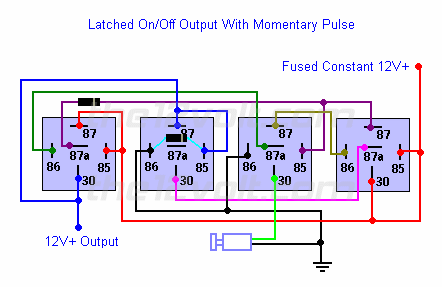
Basically the issue is when switching the latch off. It needs a very short pulse, which is possible with an extremely quick push on the button, but not really practical.
The set up I am thinking of is the latching circuit will control seperate ACC and IGN relays, starting will be done with a DEI528 timer relay. All should be switched on/off with a stock push button, which is not really a pulse.
sup22 
Member - Posts: 7
Member spacespace
Joined: May 04, 2010
Location: Arizona, United States
Posted: May 04, 2010 at 5:06 PM / IP Logged  
I'm trying to make sense of this too.... I'd like to replace the ignition key for my boat with a push button. I already have a switch to turn the batteries off completely when desired.
I picked up a (overpriced) momentary push button and (1) SPDT relay under the assumption (and guidance of generic seller instructions)that this would be all I needed to accomplish what I wanted to do. After finding this site, I now know that I am far from where I need to be. Here's what I'd like to do with a single momentary switch;
push button to turn on latched acc power and momentary to start boat
push button to turn off latched acc power and subsequently the boat
From the wiring diagrams on this site, it looks as if I need about 10 more relays to accomplish this, if at all possible. Is it possible to have a latched AND momentary circuit off the same momentary switch? The switch has 2-N.Closed and 2-N.Open circuits, along with a led + and led -
It seems it may be easier and cleaner to pick up a second switch that would be latching?
Any help with this would be greatly appreciated - thank you
miniboy 
Member - Posts: 10
Member spacespace
Joined: September 07, 2009
Posted: May 04, 2010 at 5:54 PM / IP Logged  

Sup22 Email me. I am actually wiring the set up tonight. Five relays and a momentary button gets it done.

Jaynu@aol.com

sup22 
Member - Posts: 7
Member spacespace
Joined: May 04, 2010
Location: Arizona, United States
Posted: May 04, 2010 at 7:21 PM / IP Logged  
i am an idiot wrote:
You will need an additional relay with a resistor/capacitor delay circuit.  The delay circuit will keep the relay from energizing for the first half of a second of the initial push of the button. 
 
< momentary p/b start and stop 1st post - Page 2 -- posted image.

Ok, I get all of this, but, where does the additional delay circuit fall in place in relation to the push button? Is it a completely separate circuit wired up to another of the buttons wire terminals, or can it be co-mingled with this other chain of relays? I'd assume it can go in line with all these, and it would just create a second 12v+ output?
oldspark 
Gold - Posts: 4,913
Gold spacespace
Joined: November 03, 2008
Location: Australia
Posted: May 04, 2010 at 8:31 PM / IP Logged  
Just FYI: A latching SPST relay.
One normally open button turns on.
A normally closed button turns off (or remove +12V power).
momentary p/b start and stop 1st post - Page 2 -- posted image.
miniboy 
Member - Posts: 10
Member spacespace
Joined: September 07, 2009
Posted: May 04, 2010 at 8:37 PM / IP Logged  

In my experiance you do not need a resistor delay circuit. All you need is an additional relay triggered from pin 86 on the far left relay that activated the starter(this is a ground so wire your relay as such) - Pin 87 on the relay right next to the farthest one on the left can be used to power an additional relay for an additional ignition hot (accessories, radio etc.)  THis should be all you need. It has been functioning for me in my car for quite a while.

Here is a link to the button working

http://s110.photobucket.com/albums/n107/Jaynu/Video/?action=view¤t=VID00001.flv

borischan 
Member - Posts: 5
Member spacespace
Joined: February 26, 2010
Posted: May 04, 2010 at 10:01 PM / IP Logged  
Hi miniboy, could you explain that with a diagram here or by email?
I'm still stuck with providing a pulse for the relays, pressing momentary button alone is not good enough.
Help appreciated. boris.jake@gmail.com
Thanks
sup22 
Member - Posts: 7
Member spacespace
Joined: May 04, 2010
Location: Arizona, United States
Posted: May 05, 2010 at 9:18 AM / IP Logged  
Let me see if I have this?
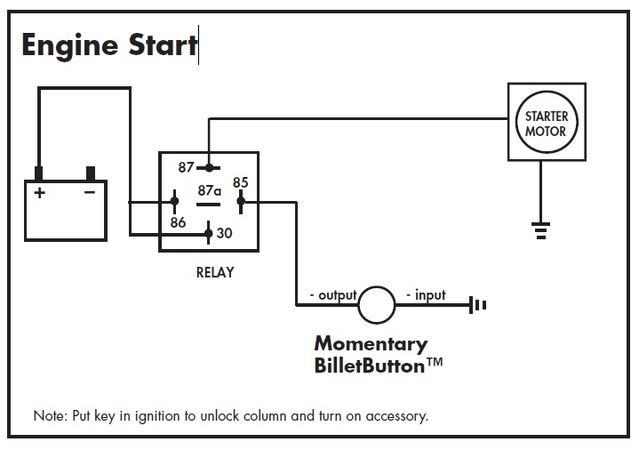
Working from these 2 diagrams, I'm going to take pin 86 from the far left relay and run it to pin 85 on a new relay, then pin 87 from relay #2 (left to right) will wire in to pins 86 & 30 on the new relay, and pin 87 from the new relay will go to the ignition wire to start the engine. This will combine the two diagrams and give me latched on/off for the accessories, and momentary to start the engine? And therefore eliminating the need for the key?
momentary p/b start and stop 1st post - Page 2 -- posted image.
sup22 
Member - Posts: 7
Member spacespace
Joined: May 04, 2010
Location: Arizona, United States
Posted: May 05, 2010 at 9:22 AM / IP Logged  
Note: the battery will not be needed on that second image.
miniboy 
Member - Posts: 10
Member spacespace
Joined: September 07, 2009
Posted: May 05, 2010 at 9:30 AM / IP Logged  
You can not wire a stand alone relay to the starter from the push button. THis will cause the starter to turn even when you want to turn the car off.  I will email the diagram I use. I can not figure out how to post it (it is a pdf)
Page of 3

  Printable version Printable version Post ReplyPost New Topic
You cannot post new topics in this forum
You cannot reply to topics in this forum
You cannot delete your posts in this forum
You cannot edit your posts in this forum
You cannot create polls in this forum
You cannot vote in polls in this forum

  •  
Search the12volt.com
Follow the12volt.com Follow the12volt.com on Facebook
Sunday, May 18, 2025 • Copyright © 1999-2025 the12volt.com, All Rights Reserved Privacy Policy & Use of Cookies
Disclaimer: *All information on this site ( the12volt.com ) is provided "as is" without any warranty of any kind, either expressed or implied, including but not limited to fitness for a particular use. Any user assumes the entire risk as to the accuracy and use of this information. Please verify all wire colors and diagrams before applying any information.

Secured by Sectigo
the12volt.com spacer
Support the12volt.com
Top
the12volt.com spacer