the12volt.com spacer
icon

sequential turn signals


Post ReplyPost New Topic
< Prev Topic Next Topic >
mikerupp 
Member - Posts: 26
Member spacespace
Joined: September 28, 2009
Posted: September 28, 2009 at 7:06 PM / IP Logged  
Hello Guys,
I have searched the forum and saw that there were a few other threads that did not pertain completely to what I am after.
Here is my problem. As it sits, I have the module to make the lights flash how I want it, but when I do use the indicator, the running lights (dim brake lights) and if pressed, the brake lights will stay lit while the indicators are activated.
What I need is for the brakes and the running lights to be completely disabled until the indicator has returned to its normal position. As in, I do not want to see the running lights in between the blinks.
I was told that I need to have the brake & the running lights on relays and then need to have a capacitor before them to make the circuit stay on while the indicator is active.
The tail lights have 4 circles. We are focusing on the last 3. The two in the middle are brakes and running lights. Both brakes are tied together for ease of wiring as well as the running lights are tied to each other. The brakes will be used as part of the sequential turn signals. So the lights will blink from inside to outside.
The indicator control module has is connected to all three and has a power input.
So if the lights were in front of you, you would see 4 different wires. Grounds, Brakes, Running and Indicator.
I really need help with the wiring diagram portion of how to I get these to blink like the older cars or the brand new Mustangs.
If I did not make this clear enough please ask me to clarify. I am just learning the electrical lingo.
Thank you in advance,
d_rock_81 
Member - Posts: 39
Member spacespace
Joined: June 09, 2009
Location: North Dakota, United States
Posted: September 28, 2009 at 11:08 PM / IP Logged  
What kind of vehicle??
Dustin Rockney
Rockstar Autosports
mikerupp 
Member - Posts: 26
Member spacespace
Joined: September 28, 2009
Posted: September 29, 2009 at 5:32 PM / IP Logged  
94 Toyota Supra Turbo
Even though I dont think that matters.
KPierson 
Platinum - Posts: 3,527
Platinum spaceThis member consistently provides reliable informationspace
Joined: April 14, 2005
Location: Ohio, United States
Posted: September 29, 2009 at 8:45 PM / IP Logged  

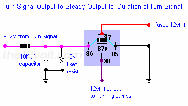
Not very elegent, but this should work:

sequential turn signals -- posted image.

You can use the 12vdc output to energize more relays - one relay to cut each signal you need to cut.

Kevin Pierson
i am an idiot 
Platinum - Posts: 13,667
Platinum spaceThis member consistently provides reliable informationspace
Joined: September 21, 2006
Location: Louisiana, United States
Posted: September 29, 2009 at 8:52 PM / IP Logged  

When you say the 2 middle ones are brake and tail light, one on each side of the vehicle?   Or one for brake and one for tail on each side of the vehicle?   This will be easy, I just need the above answers.

mikerupp 
Member - Posts: 26
Member spacespace
Joined: September 28, 2009
Posted: September 30, 2009 at 4:10 PM / IP Logged  
i am an idiot wrote:

When you say the 2 middle ones are brake and tail light, one on each side of the vehicle?   Or one for brake and one for tail on each side of the vehicle?   This will be easy, I just need the above answers.

Yes, I am referring to the two inside circles of each tail light. So I would want to cut out both of these on each side.
sequential turn signals -- posted image.
i am an idiot 
Platinum - Posts: 13,667
Platinum spaceThis member consistently provides reliable informationspace
Joined: September 21, 2006
Location: Louisiana, United States
Posted: September 30, 2009 at 4:20 PM / IP Logged  
And you want to have the brake and tail portion go out and remain out while the blinkers are on?   But you want the brake and tail light elements to operate as two of the 3 bulbs in the sequence of the blinkers, is this correct?
Which of the elements do you want to work as the blinker?  The parking lamp or the brake lamp?  I think we can do this with 3 relays per side.
mikerupp 
Member - Posts: 26
Member spacespace
Joined: September 28, 2009
Posted: September 30, 2009 at 6:19 PM / IP Logged  
i am an idiot wrote:
And you want to have the brake and tail portion go out and remain out while the blinkers are on?   But you want the brake and tail light elements to operate as two of the 3 bulbs in the sequence of the blinkers, is this correct?
Which of the elements do you want to work as the blinker?  The parking lamp or the brake lamp?  I think we can do this with 3 relays per side.
To use the pictures above as a reference I will explain what I am looking at doing on JUST THE PASSENGER LIGHT.
The left clear lens would be reverse ( FORGET ABOUT THIS ), the next two are used for running lights(dimmer) as well as brakes (brighter and my main focus) and the outer clear lens is the normal turn signal.
I have a control module that has the lights blink from inside to outside. So they are all set for that. The lights are LED's now and I have it set up on the circuit boards so that the control module can send a signal to each board in the specific sequence.
i am an idiot 
Platinum - Posts: 13,667
Platinum spaceThis member consistently provides reliable informationspace
Joined: September 21, 2006
Location: Louisiana, United States
Posted: October 03, 2009 at 7:15 PM / IP Logged  

you will have to build the setup that Kevin posted earlier.  That will give you a constant output to power the other relays.  I did not realize that there were 2 for tail and the same 2 (different elements) for brakes.  This will take 3 relays plus the one Kevin posted per side of the vehicle. 

Wire the third output from the module directly to the blinker lamp.  You will have to wire a relay to kill the tail lights when the blinker is on.  Wire it as follows.  Cut the wire before the lamp, connect one end to terminal 30 of the relay.  Connect the other end to terminal 87A.  Connect the output of Kevin's diagram to terminal 86 of all 3 relays on that side.  Ground terminal 85 of all 3 relays.   You said earlier that there was one wire for the brake and one wire for the tail lights.  You should connect both tail light elements to the one relay.  You will need 2 relays for the brake elements. 

For the brake light elements, do just as you did for the tail lights except you need 2 relays, and this time it is crucial that the lamp is connected to terminal 30 and the wire that comes from the car goes to terminal 87A.  Now on the relay on the inner brake light connect the first output of the module to terminal 87.  On the relay connected to the middle brake lamp, (middle element of your blinker setup), connect the second output of your module to terminal 87.

mikerupp 
Member - Posts: 26
Member spacespace
Joined: September 28, 2009
Posted: October 04, 2009 at 1:28 PM / IP Logged  
i am an idiot wrote:

you will have to build the setup that Kevin posted earlier.  That will give you a constant output to power the other relays.  I did not realize that there were 2 for tail and the same 2 (different elements) for brakes.  This will take 3 relays plus the one Kevin posted per side of the vehicle. 

Wire the third output from the module directly to the blinker lamp.  You will have to wire a relay to kill the tail lights when the blinker is on.  Wire it as follows.  Cut the wire before the lamp, connect one end to terminal 30 of the relay.  Connect the other end to terminal 87A.  Connect the output of Kevin's diagram to terminal 86 of all 3 relays on that side.  Ground terminal 85 of all 3 relays.   You said earlier that there was one wire for the brake and one wire for the tail lights.  You should connect both tail light elements to the one relay.  You will need 2 relays for the brake elements. 

For the brake light elements, do just as you did for the tail lights except you need 2 relays, and this time it is crucial that the lamp is connected to terminal 30 and the wire that comes from the car goes to terminal 87A.  Now on the relay on the inner brake light connect the first output of the module to terminal 87.  On the relay connected to the middle brake lamp, (middle element of your blinker setup), connect the second output of your module to terminal 87.

Thanks!!!
Cant believe I am going to take advice from an idiot!! sequential turn signals -- posted image.
Appreciate the help.
Page of 5

  Printable version Printable version Post ReplyPost New Topic
You cannot post new topics in this forum
You cannot reply to topics in this forum
You cannot delete your posts in this forum
You cannot edit your posts in this forum
You cannot create polls in this forum
You cannot vote in polls in this forum

  •  
Search the12volt.com
Follow the12volt.com Follow the12volt.com on Facebook
Monday, April 29, 2024 • Copyright © 1999-2024 the12volt.com, All Rights Reserved Privacy Policy & Use of Cookies
Disclaimer: *All information on this site ( the12volt.com ) is provided "as is" without any warranty of any kind, either expressed or implied, including but not limited to fitness for a particular use. Any user assumes the entire risk as to the accuracy and use of this information. Please verify all wire colors and diagrams before applying any information.

Secured by Sectigo
the12volt.com spacer
Support the12volt.com
Top
the12volt.com spacer