the12volt.com spacer
icon

sequential turn signals


Post ReplyPost New Topic
< Prev Topic Next Topic >
i am an idiot 
Platinum - Posts: 13,667
Platinum spaceThis member consistently provides reliable informationspace
Joined: September 21, 2006
Location: Louisiana, United States
Posted: October 04, 2009 at 3:39 PM / IP Logged  
Let us know how it works out. 
mikerupp 
Member - Posts: 26
Member spacespace
Joined: September 28, 2009
Posted: October 04, 2009 at 5:23 PM / IP Logged  
I wanted to make a visual diagram before I jump into it. Can you tell me if this looks accurate?
sequential turn signals - Page 2 -- posted image.
i am an idiot 
Platinum - Posts: 13,667
Platinum spaceThis member consistently provides reliable informationspace
Joined: September 21, 2006
Location: Louisiana, United States
Posted: October 04, 2009 at 5:32 PM / IP Logged  

I thought you were using the brake light elements as the blinkers.  Is this correct?  According to what you drew, you have the module connected to the lights.  In my instructions the module is to be connected to the relays.  When the blinkers are turned on, the relays are energized, which breaks the connection to the tail and brake light feeds.  The relays then connect 87 to the lights.  When the module sends a signal to 87, that will light that blinker. 

i am an idiot 
Platinum - Posts: 13,667
Platinum spaceThis member consistently provides reliable informationspace
Joined: September 21, 2006
Location: Louisiana, United States
Posted: October 04, 2009 at 5:38 PM / IP Logged  

I will draw you a picture tonight.

Are you planning to use the brake light elements as the blinkers?  Or are you just wanting to turn the brake lights off during the blinker cycles? 

Just to avoid confusion on the diagrams, I am going to draw one for the taillights and a separate for the brake light elements.

mikerupp 
Member - Posts: 26
Member spacespace
Joined: September 28, 2009
Posted: October 04, 2009 at 5:46 PM / IP Logged  
Yes the module will control each individual light to blink in the proposed fashion.
The brakes will be wired together to have one wire.
The running lights will be wired together to have one wire.
When I hit the turn signal to ON I want both of the brakes and/or running lights to turn off immediately, not one by one, until the turn signal is off.
Let me take a whack at this diagram again.
mikerupp 
Member - Posts: 26
Member spacespace
Joined: September 28, 2009
Posted: October 04, 2009 at 5:47 PM / IP Logged  
let me see if I can photoshop something up to show exactly what I am after.
i am an idiot 
Platinum - Posts: 13,667
Platinum spaceThis member consistently provides reliable informationspace
Joined: September 21, 2006
Location: Louisiana, United States
Posted: October 04, 2009 at 6:03 PM / IP Logged  

I need to know if you are planning on using the brake light elements as your blinkers?  Or is there a dedicated blinker element and you just need to kill the brake and tail lights?

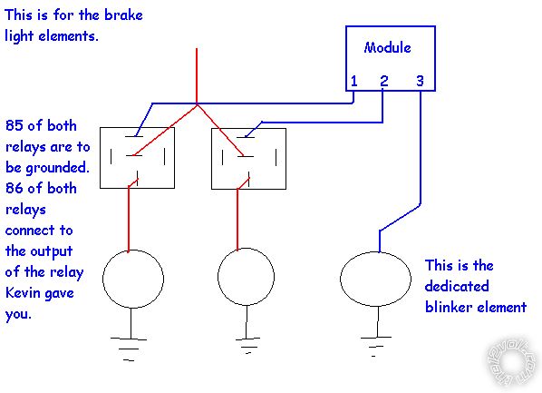
The following diagram is assuming that you are using the brighter brake light elements as your blinkers.  You have to wire them up independent of the other one because you are using them as 2 different elements of the blinkers. 

The red wire coming from the top of the picture is the brake light wire coming from the car.

sequential turn signals - Page 2 -- posted image.

i am an idiot 
Platinum - Posts: 13,667
Platinum spaceThis member consistently provides reliable informationspace
Joined: September 21, 2006
Location: Louisiana, United States
Posted: October 04, 2009 at 6:14 PM / IP Logged  

sequential turn signals - Page 2 -- posted image.

Thanks fot the 200K upload size. 

mikerupp 
Member - Posts: 26
Member spacespace
Joined: September 28, 2009
Posted: October 04, 2009 at 6:20 PM / IP Logged  
I will not be using the wires for the brakes or the running lights. As I added my own to the custom circuit boards using LED's. So, yes I will be using a dedicated blinker wire for each light. I just need to kill the brakes and the running lights, correct.
A close look at just one of the brake light circuit boards and you will see a single wire for running lights, a single wire for brake lights, a single wire for the turn signal input, and a ground.
You will have that same thing again on the other brake light circuit board.
So, when I would turn the indicators on I would want the brakes to shut off completely and take the signal ONLY from the control module.
sequential turn signals - Page 2 -- posted image.
i am an idiot 
Platinum - Posts: 13,667
Platinum spaceThis member consistently provides reliable informationspace
Joined: September 21, 2006
Location: Louisiana, United States
Posted: October 04, 2009 at 6:36 PM / IP Logged  
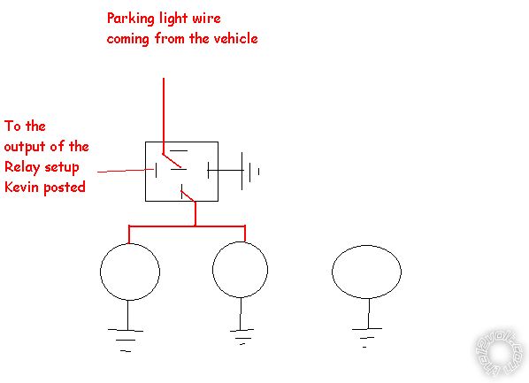
Use my last drawing twice.  One for the brake light wire and once for the tail light wire. 
Page of 5

  Printable version Printable version Post ReplyPost New Topic
You cannot post new topics in this forum
You cannot reply to topics in this forum
You cannot delete your posts in this forum
You cannot edit your posts in this forum
You cannot create polls in this forum
You cannot vote in polls in this forum

  •  
Search the12volt.com
Follow the12volt.com Follow the12volt.com on Facebook
Monday, April 29, 2024 • Copyright © 1999-2024 the12volt.com, All Rights Reserved Privacy Policy & Use of Cookies
Disclaimer: *All information on this site ( the12volt.com ) is provided "as is" without any warranty of any kind, either expressed or implied, including but not limited to fitness for a particular use. Any user assumes the entire risk as to the accuracy and use of this information. Please verify all wire colors and diagrams before applying any information.

Secured by Sectigo
the12volt.com spacer
Support the12volt.com
Top
the12volt.com spacer