Posted: September 28, 2009 at 11:14 PM / IP Logged
Posted: September 29, 2009 at 5:32 AM / IP Logged
Sorry, you can NOT post a reply.
This topic is closed.
 Printable version


| You cannot post new topics in this forum You cannot reply to topics in this forum You cannot delete your posts in this forum You cannot edit your posts in this forum You cannot create polls in this forum You cannot vote in polls in this forum |

| Search the12volt.com |
Follow the12volt.com 
Saturday, January 24, 2026 • Copyright © 1999-2026 the12volt.com, All Rights Reserved • Privacy Policy & Use of Cookies


Saturday, January 24, 2026 • Copyright © 1999-2026 the12volt.com, All Rights Reserved • Privacy Policy & Use of Cookies
Disclaimer:
*All information on this site ( the12volt.com ) is provided "as is" without any warranty of any kind, either expressed or implied, including but not limited to fitness for a particular use. Any user assumes the entire risk as to the accuracy and use of this information. Please
verify all wire colors and diagrams before applying any information.


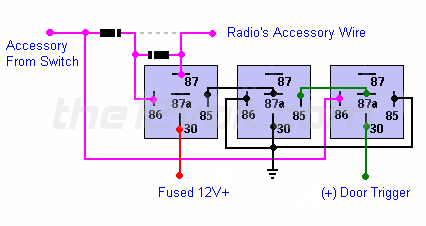
 but i'm new to these diagrams and i'm not sure exactly where to put the two diodes that it says it needs. I'm going to attempt to walk through the diagram so please correct me if i'm wrong:
i'm going to take the wire that turns the radio on that comes from the accessory circuit and hook it up
first to pin 86 on the far-right relay
on the far left relay, i'm going to put a diode between the accessory circuit and pin 86, and i'm going to put another diode AFTER the first diode connecting pins 86 and 87, and the radio is connected to pin 87.
all the rest of the connections are self-explanatory enough for me to wrap my head around, but am i thinking correctly about the diodes?
ALSO I need to know if anybody has information on where i can tap the door trigger wire?
Thanks


