


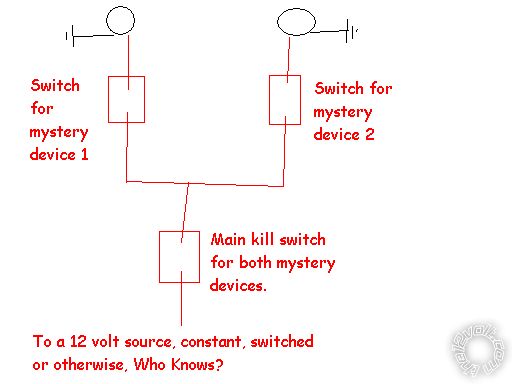
two seprate circuits, one switch?
Home /
the12volt's Install Bay /
Lights, Neon, LEDs, HIDs / two seprate circuits, one switch? ( Topic Closed)


Posted: November 28, 2009 at 11:06 PM / IP Logged


Posted: November 28, 2009 at 11:40 PM / IP Logged

Posted: November 29, 2009 at 12:26 AM / IP Logged
Posted: November 29, 2009 at 1:28 AM / IP Logged
Posted: November 29, 2009 at 7:33 AM / IP Logged
Posted: November 29, 2009 at 8:18 AM / IP Logged


Posted: December 02, 2009 at 6:44 PM / IP Logged
Posted: December 02, 2009 at 7:02 PM / IP Logged
Posted: December 02, 2009 at 8:48 PM / IP Logged
Posted: December 02, 2009 at 10:32 PM / IP Logged
 As to the importance of the current being switched, maybe it's because I break solution down into respective parts, but I agree with...
 Printable version
| You cannot post new topics in this forum You cannot reply to topics in this forum You cannot delete your posts in this forum You cannot edit your posts in this forum You cannot create polls in this forum You cannot vote in polls in this forum |

| Search the12volt.com |
Follow the12volt.com 
Thursday, May 7, 2026 • Copyright © 1999-2026 the12volt.com, All Rights Reserved • Privacy Policy & Use of Cookies

Thursday, May 7, 2026 • Copyright © 1999-2026 the12volt.com, All Rights Reserved • Privacy Policy & Use of Cookies
Disclaimer:
*All information on this site ( the12volt.com ) is provided "as is" without any warranty of any kind, either expressed or implied, including but not limited to fitness for a particular use. Any user assumes the entire risk as to the accuracy and use of this information. Please
verify all wire colors and diagrams before applying any information.
