the12volt.com spacer
icon

intercom wiring


Post ReplyPost New Topic
< Prev Topic Next Topic >
dualsport 
Silver - Posts: 983
Silver spacespace
Joined: September 27, 2005
Location: United States
Posted: January 10, 2010 at 4:32 PM / IP Logged  
Good point- maybe the unit he has isn't as shown in the diagram I found. Either way, it's not as described. Certainly a set of dry contacts can't drive a door strike, so they're definitely not dry contacts.
If they can drive the strike when directly connected, but can't do it with just the red output connected, then it seems the thing to try would be to see what that black output is doing. Possibly just need to connect it to the ground side of the door strike. Then it's the same as a direct connection. If it doesn't work then, there's more going on in there that we'd need to find out about.
sumnerhousesf 
Member - Posts: 6
Member spacespace
Joined: January 09, 2010
Location: California, United States
Posted: January 10, 2010 at 4:37 PM / IP Logged  
Yes when wired individually both systems work. The diagram you show is for a different model of doorfone. I have a DP28 2 button intercom with a built in door strike controller so I dont need the extra box.
You may have something there though with the extra relay. Would I need a SPDT or DPDT relay for this? thanks a lot
i am an idiot 
Platinum - Posts: 13,670
Platinum spaceThis member consistently provides reliable informationspace
Joined: September 21, 2006
Location: Louisiana, United States
Posted: January 10, 2010 at 4:45 PM / IP Logged  
If the unit will open the lock when connected without the keypad, the relay should not be neccesary.  Hey I have an idea, check for continuity between the common and the normally closed connections of the keypad.  You may have a defective relay or an open trace or a bad connection on the back of the circuit board of the keypad.
dualsport 
Silver - Posts: 983
Silver spacespace
Joined: September 27, 2005
Location: United States
Posted: January 10, 2010 at 4:47 PM / IP Logged  
Can you make a couple measurements with a meter to see if we can see what it's actually putting out?
In your other thread, you indicated if you swap the wire around so that you're running the black wire to the keypad, the door strike is continually energized. This indicates the black output actually has 12V on it continually.
The red wire probably is a shunt to ground when the doorfone is active.
If this is the case, then you'd just need to change it around to use ground switching for your door strike rather than (+) switching.
dualsport 
Silver - Posts: 983
Silver spacespace
Joined: September 27, 2005
Location: United States
Posted: January 10, 2010 at 4:48 PM / IP Logged  
I assume you know how to reconfigure it for ground switching, but if not, we could draw it up for you-
sumnerhousesf 
Member - Posts: 6
Member spacespace
Joined: January 09, 2010
Location: California, United States
Posted: January 10, 2010 at 5:08 PM / IP Logged  
Yes the - door contact outputs 12v continually. Sorry I am a novice at this hence so many questions. Can you tell me how to wire it for ground switching with both units connected?
dualsport 
Silver - Posts: 983
Silver spacespace
Joined: September 27, 2005
Location: United States
Posted: January 10, 2010 at 5:34 PM / IP Logged  
intercom wiring - Page 2 -- posted image.
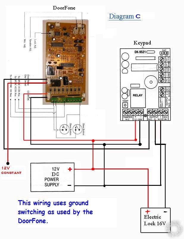
Note I changed the colors of the wires coming out from the door fone, but the terminals should be how you found it originally-
The red wire is now the +12V constant, and the black is the switched ground output-
sumnerhousesf 
Member - Posts: 6
Member spacespace
Joined: January 09, 2010
Location: California, United States
Posted: January 10, 2010 at 6:00 PM / IP Logged  
OMG! that's genius. Thanks for the wonderful diagram. I will try it and let you know how it goes. I would have never been able to figure it out on my own, but it makes perfect sense. I'm hopeful about this one
dualsport 
Silver - Posts: 983
Silver spacespace
Joined: September 27, 2005
Location: United States
Posted: January 10, 2010 at 6:10 PM / IP Logged  
intercom wiring - Page 2 -- posted image.
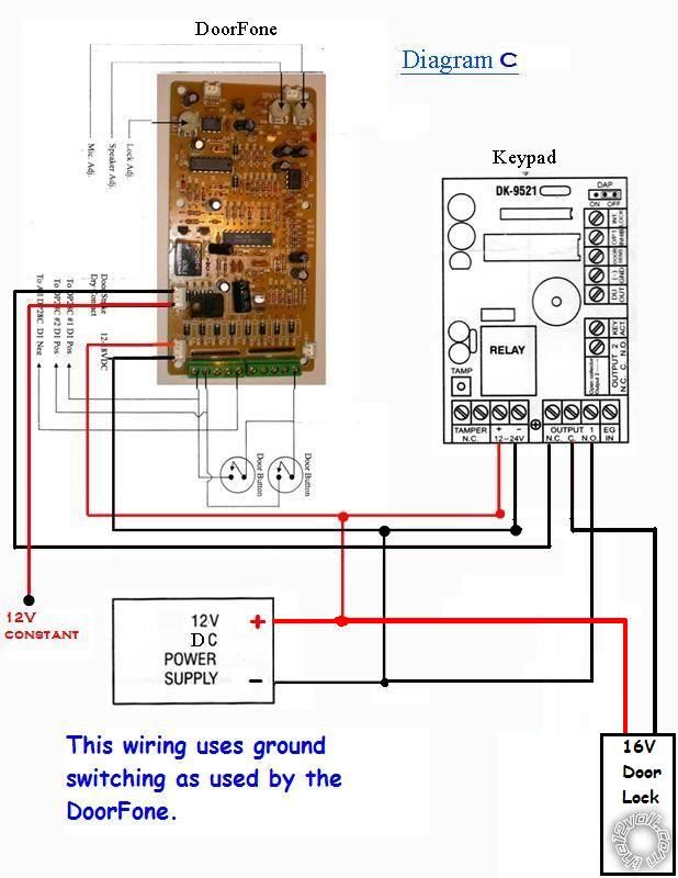
And now you have a customized door lock -intercom wiring - Page 2 -- posted image.
Hope it works out!
Page of 2

Sorry, you can NOT post a reply.
This topic is closed.

  Printable version Printable version Post ReplyPost New Topic
You cannot post new topics in this forum
You cannot reply to topics in this forum
You cannot delete your posts in this forum
You cannot edit your posts in this forum
You cannot create polls in this forum
You cannot vote in polls in this forum

  •  
Search the12volt.com
Follow the12volt.com Follow the12volt.com on Facebook
Saturday, May 4, 2024 • Copyright © 1999-2024 the12volt.com, All Rights Reserved Privacy Policy & Use of Cookies
Disclaimer: *All information on this site ( the12volt.com ) is provided "as is" without any warranty of any kind, either expressed or implied, including but not limited to fitness for a particular use. Any user assumes the entire risk as to the accuracy and use of this information. Please verify all wire colors and diagrams before applying any information.

Secured by Sectigo
the12volt.com spacer
Support the12volt.com
Top
the12volt.com spacer