the12volt.com spacer
icon

pcb components for dei brains?


Post ReplyPost New Topic
< Prev Topic Next Topic >
bruno molly 
Member - Posts: 20
Member spacespace
Joined: November 11, 2009
Location: North Carolina, United States
Posted: February 02, 2010 at 1:32 PM / IP Logged  
Does DEI sell Circuit board components for there Alarm/keyless entry Brains? I have 3 with smoked resistors on the Trunk Release output. Either 10 ohms or 9.5 ohms is what a good one reads. I am getting no (-) output on the output side (terminal), but I do get an output on the good side of the resistor. [100]is printed on the component, a SMD tiny resistor. Anyone ever encounter this? I can get the part from Digikey if I had the specs. Not sure if they will release that information. Emailed them yesterday but haven't gotten a reply.
Thanks
-=Molly
The Sky is not the limit....The Ground is!
Ween 
Platinum - Posts: 1,366
Platinum spacespace
Joined: August 01, 2004
Location: Illinois, United States
Posted: February 02, 2010 at 2:49 PM / IP Logged  

what model is the unit? maybe someone here has the same piece that they could peek inside and take a look.  post a pic of the board in the area of the burned up part?

m

KPierson 
Platinum - Posts: 3,527
Platinum spaceThis member consistently provides reliable informationspace
Joined: April 14, 2005
Location: Ohio, United States
Posted: February 02, 2010 at 3:35 PM / IP Logged  

Chances are the actual value of the resistor isn't all that critical (or you wouldn't have three burnt up ones).

Kidding aside, I would see if you can trace out the circuit - if it is trunk output it most likely goes from the processor, through the burnt resistor, then to a darlington transistor array.  The resistor is probably there to protect the transistor it drives (by limiting the current in you limit the current out). 

I would guess you would have no luck at all with DEI in getting components, especially since they have lifetime warranties on most of their brains.

Kevin Pierson
bruno molly 
Member - Posts: 20
Member spacespace
Joined: November 11, 2009
Location: North Carolina, United States
Posted: February 02, 2010 at 4:00 PM / IP Logged  
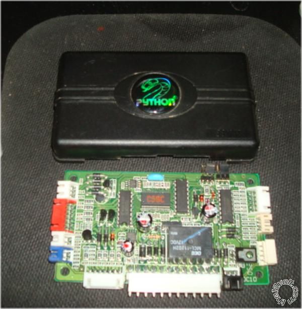
pcb components for dei brains? -- posted image.
Python model 881XP
pcb components for dei brains? -- posted image.
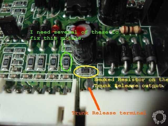
The Resistor to the left circled in Green is the part that is Identical to the smoked one that I need. [100].
I measure 9.5 ohms on all of them without removing them.
The Smoked one now measure 200K ohms.
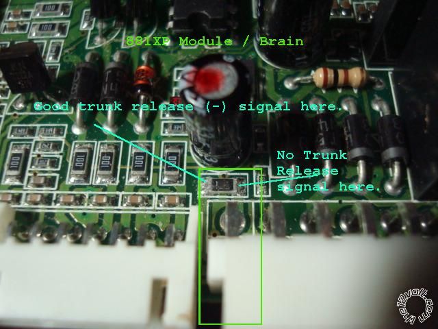
I can get a good reading on the signal presentation side, but no signal thru the smoked resistor.
pcb components for dei brains? -- posted image.
Anyone have any Fried Brains or cannibalized units
that you may want to get rid of let me know. Or, knowing the
true Value, Size, Material its made of (Thin Film is my guess) Wattage, Case style, we can see its a Surface Mounted Device (SMD) and tolerance (+ - 5% 10% etc)of this resistor would
be helpful to know.
Thanks for your help!
-=Molly
The Sky is not the limit....The Ground is!
bruno molly 
Member - Posts: 20
Member spacespace
Joined: November 11, 2009
Location: North Carolina, United States
Posted: February 02, 2010 at 4:11 PM / IP Logged  
What happened was this... The guy who was testing these out, used a TAPED up DEI Harness, and some Knuckle head had Soldered the RED / White wire (Trunk Release which is a (-) output), To the RED wire next to it, the Constant +12V. So when he activated the Trunk relase with our Test rig, the bulb we used to test the output didn't light up, and we smelled the Inevitable! This is how we got 3 Toasted Brains on this output. Bypassing the Resistor it works like a charm.
The 2nd unit is a Viper 791xv, and the 3rd unit is an Avital 3300.
I Really on need 3 resistors but I always like to have extras.
-=Molly
The Sky is not the limit....The Ground is!
KPierson 
Platinum - Posts: 3,527
Platinum spaceThis member consistently provides reliable informationspace
Joined: April 14, 2005
Location: Ohio, United States
Posted: February 02, 2010 at 4:59 PM / IP Logged  

ok, I was wrong with what I said above, the resistor is on the collector side of the transistor, used to limit current on the output (to roughly 1.41A).  What voltage were you testing at? 

I would get on digikey and order several 10 ohm surface mount resistors and see what fits. 

You figure 10 ohms at 15vdc will allow 1.5A to flow through it.  1.5 * 15 = 22 watts.  Something doesn't sound right there (which is why you have burnt up resistors).  It almost seems like they are using the resistors more as fuses then resistors.

I believe the output is rated at 200mA.  .2 * 15 = 3 watts.  That is still high, but much more believable.

If you want to try to get more precise mic the resistor and then find the correct footprint in the datasheet.

Kevin Pierson
t&t tech 
Platinum - Posts: 2,608
Platinum spacespace
Joined: October 05, 2008
Location: Trinidad and Tobago
Posted: February 02, 2010 at 6:11 PM / IP Logged  
That output is rated at 200ma!
commit your way to jehovah and he will act in your behalf. psalms 37:5
jeffwhiteman 
Copper - Posts: 124
Copper spacespace
Joined: October 20, 2006
Location: United States
Posted: February 03, 2010 at 1:56 PM / IP Logged  
surface mount resistors are marked with a 3 digit code. (100) the first 2 numbers are the value and the third number is the power of ten (number of zeros) so 100= 10 ohms and 101= 100 ohms.
If you dont want to wait for an order you could remove the burnt resistor , solder some leads to the board, then attach a standard radioshack resistor(tape off the exposed leads and stuff it in the box.)
I do however suspect something caused excessive current to flow through them though, but its worth a try.
bruno molly 
Member - Posts: 20
Member spacespace
Joined: November 11, 2009
Location: North Carolina, United States
Posted: February 03, 2010 at 8:52 PM / IP Logged  
Ok...Thanks for that informative explanation!! I was wondering. Resistors have come a long way from those color bands. I bought some from RS today.
The Sky is not the limit....The Ground is!

Sorry, you can NOT post a reply.
This topic is closed.

  Printable version Printable version Post ReplyPost New Topic
You cannot post new topics in this forum
You cannot reply to topics in this forum
You cannot delete your posts in this forum
You cannot edit your posts in this forum
You cannot create polls in this forum
You cannot vote in polls in this forum

  •  
Search the12volt.com
Follow the12volt.com Follow the12volt.com on Facebook
Wednesday, April 24, 2024 • Copyright © 1999-2024 the12volt.com, All Rights Reserved Privacy Policy & Use of Cookies
Disclaimer: *All information on this site ( the12volt.com ) is provided "as is" without any warranty of any kind, either expressed or implied, including but not limited to fitness for a particular use. Any user assumes the entire risk as to the accuracy and use of this information. Please verify all wire colors and diagrams before applying any information.

Secured by Sectigo
the12volt.com spacer
Support the12volt.com
Top
the12volt.com spacer