the12volt.com spacer
icon

door actuator wiring


Post ReplyPost New Topic
< Prev Topic Next Topic >
frexe 
Member - Posts: 13
Member spacespace
Joined: February 19, 2010
Posted: February 23, 2010 at 1:40 PM / IP Logged  
I have the relays wired up exactly like the diagram. But the fuse blows every time.
moonliter 
Copper - Posts: 322
Copper spacespace
Joined: February 28, 2007
Location: Canada
Posted: February 23, 2010 at 2:00 PM / IP Logged  

Why dont you disconnect the actuators & try. If the fuse blows again, then definitely you had the relays wired wrong. Possibly you got the 30's & 87's mixed up. If they are good then check your actuators, make sure they are not stuck.

t&t tech 
Platinum - Posts: 2,608
Platinum spacespace
Joined: October 05, 2008
Location: Trinidad and Tobago
Posted: February 23, 2010 at 3:00 PM / IP Logged  
Even if the actuators are stuck this shouldn't cause the fuse to pop! Do as moonliter said and disconnect the actuators from the relays, however disconnect it at the relay and not at the motor, since it maybe a case of one of the motor wires shorted to the body through the door boot rubber! Notice the key word MAYBE!
commit your way to jehovah and he will act in your behalf. psalms 37:5
howie ll 
Pot Metal - Posts: 16,466
Pot Metal spacespace
Joined: January 09, 2007
Location: United Kingdom
Posted: February 23, 2010 at 4:25 PM / IP Logged  
All actuators or motors or solenoids or simply door lock motors are reversing polarity. One leg sits on ground whilst the other side is pulsed pos.To reverse the motion the second side stays neg whilst the first side is pulsed pos. Yes I'm not counting pneumatic "pumps" as used on M/Benz and VAG cars.
frexe 
Member - Posts: 13
Member spacespace
Joined: February 19, 2010
Posted: February 24, 2010 at 2:26 AM / IP Logged  
door actuator wiring - Page 2 -- posted image.
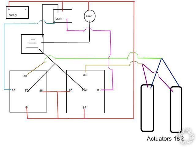
Okay I have drawn up my wiring.
Note:
-without the two actuator relays connected, the alarm and siren both work fine.
-with the relays connected the fuse shorts instantly.
-I have tried 30amp fuse.
-I have tried with the actuators disconnected.
-My relay wiring has been checked a million times.
My hypothesis is that there is some critical error in my diagram that you guys can easily spot. Hence the poor drawing.
Supplemental/irrelevant information
The brain is a cm6200 Remote start.
I have the Remote start working.
1991 mazda miata.
The 12v is drawn straight from the battery fused. (this is the fuse that keeps popping.
I have tested the relay for continuity. just testing pins 85 and 86 = no continuity. And just testing pins 85 and 86, they also have no continuity. So this should rule out that area of the relays I am supplying power?
Thanks for the help.
howie ll 
Pot Metal - Posts: 16,466
Pot Metal spacespace
Joined: January 09, 2007
Location: United Kingdom
Posted: February 24, 2010 at 4:40 AM / IP Logged  
Please do this, try it with one relay at a time or do the following:-
At rest 87a and 30 should be continuous. 30 and 87 aren't.
When the coil, 85 (-) and 86 (+) are connected, the circuit between 87a and 30 "breaks" and between 30 and 87 it "makes". 87a should NEVER connect to 87. Then still using your meter, still on continuity setting, join 1 lead to a good ground and the other lead to each motor wire in turn (with the motor wires disconnected). You should get no continuity. If you do that lead is shorting and that's your problem. If all of this fails, then please recheck your wiring, sorry, 35 years of experience tells me that if a fuse blows, something's in the wrong place! Last but not least you mentioned these relays were salvaged, nothing wrong there, the failure rate is one in millions. Had some 3 0r 4 fuel pump primer relays fail on Porsche and some Fords in the mid 90s but that was probably a Bosch or Hella batch problem, BUT check the connections, proprietary relays sometimes transpose 30 and 85, also make sure it's an 87a not 87b.
i am an idiot 
Platinum - Posts: 13,667
Platinum spaceThis member consistently provides reliable informationspace
Joined: September 21, 2006
Location: Louisiana, United States
Posted: February 24, 2010 at 5:29 AM / IP Logged  

door actuator wiring - Page 2 -- posted image.

As stated earlier, make sure you have the relays oriented properly.  30 is at the bottom of both relays in the above diagram.  If you have the relays upside down, it WILL blow a fuse everytime you insert the fuse.

jmkelly_us 
Member - Posts: 1
Member spacespace
Joined: August 07, 2006
Location: North Carolina, United States
Posted: February 24, 2010 at 2:52 PM / IP Logged  
I am having the same problem. But it is not the 12+ fuse that is popping. It is the fuse coming out of the alarm. Any ideas why this would be happening. I have mine wired exactly the same way. I can get one part to work, either the unlock or lock, but the other will blow the fuse. The last questions is what amp fuse should be used for the relays?
t&t tech 
Platinum - Posts: 2,608
Platinum spacespace
Joined: October 05, 2008
Location: Trinidad and Tobago
Posted: February 24, 2010 at 4:00 PM / IP Logged  

jmkelly_us wrote:
I am having the same problem. But it is not the 12+ fuse that is popping. It is the fuse coming out of the alarm. Any ideas why this would be happening. I have mine wired exactly the same way. I can get one part to work, either the unlock or lock, but the other will blow the fuse. The last questions is what amp fuse should be used for the relays?

The amperage of the fuse will depend on the amount of solenoids in your circuit! Also you should start your own thread, as this may distract from assisting the OP!

commit your way to jehovah and he will act in your behalf. psalms 37:5
frexe 
Member - Posts: 13
Member spacespace
Joined: February 19, 2010
Posted: February 24, 2010 at 6:10 PM / IP Logged  
^quadruple check your wiring. If its correct...
What kind of output for lock and unlock does your alarm send out?
Ah I read somewhere that if the solenoid is seizing it may draw extra power and cause the fuse to blow. Check if that applies.
I got a giant DMM..but I haven't a clue how to use it
Page of 3

  Printable version Printable version Post ReplyPost New Topic
You cannot post new topics in this forum
You cannot reply to topics in this forum
You cannot delete your posts in this forum
You cannot edit your posts in this forum
You cannot create polls in this forum
You cannot vote in polls in this forum

  •  
Search the12volt.com
Follow the12volt.com Follow the12volt.com on Facebook
Friday, April 26, 2024 • Copyright © 1999-2024 the12volt.com, All Rights Reserved Privacy Policy & Use of Cookies
Disclaimer: *All information on this site ( the12volt.com ) is provided "as is" without any warranty of any kind, either expressed or implied, including but not limited to fitness for a particular use. Any user assumes the entire risk as to the accuracy and use of this information. Please verify all wire colors and diagrams before applying any information.

Secured by Sectigo
the12volt.com spacer
Support the12volt.com
Top
the12volt.com spacer