


using relay to power up high beam


Posted: March 29, 2010 at 12:56 AM / IP Logged


Posted: March 29, 2010 at 2:14 AM / IP Logged
Posted: March 29, 2010 at 2:21 AM / IP Logged
Posted: March 29, 2010 at 2:53 AM / IP Logged

Posted: March 29, 2010 at 3:19 AM / IP Logged
Posted: March 29, 2010 at 3:41 AM / IP Logged

Posted: March 29, 2010 at 8:19 AM / IP Logged
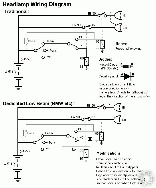
 The next shows the above using identical SPST relays that could be swapped if it's the most desireable beam that fails (ie, usually low beam - replace failed lo-beam relay with the hi-beam's).
Also failure of one relay does no effect the other beam.
It shows the TWO topologies for a 4-headlight system - namely dedicated lo-beam or combined hi&lo-beam for one pair (and dedicated hi-beam for the other pair).
The upper "Traditional" depicts H4 type hi-lo bulbs and the dashed line between lo & hi means the hi-beam power (for the hi in the "Lo" which should probably be called outer or upper beams). (It can also take me a while to decipher his diagrams!)
The lower is the (modern) equivalent where the beams are a dedicated lo-beam, ie, a single filament bulb etc. They remain on when the hi-beam is on. (This does not occur in dual-filament bulbs like H4 as they would overheat, though they may both light in "flash" (passing) mode...)
The next shows the above using identical SPST relays that could be swapped if it's the most desireable beam that fails (ie, usually low beam - replace failed lo-beam relay with the hi-beam's).
Also failure of one relay does no effect the other beam.
It shows the TWO topologies for a 4-headlight system - namely dedicated lo-beam or combined hi&lo-beam for one pair (and dedicated hi-beam for the other pair).
The upper "Traditional" depicts H4 type hi-lo bulbs and the dashed line between lo & hi means the hi-beam power (for the hi in the "Lo" which should probably be called outer or upper beams). (It can also take me a while to decipher his diagrams!)
The lower is the (modern) equivalent where the beams are a dedicated lo-beam, ie, a single filament bulb etc. They remain on when the hi-beam is on. (This does not occur in dual-filament bulbs like H4 as they would overheat, though they may both light in "flash" (passing) mode...)
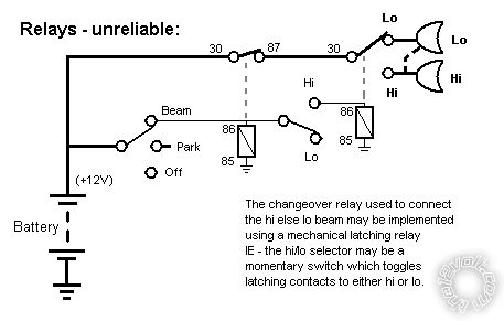
 Hopefully you'll see how the "unreliable" wiring to the RHS of the first relay (RHS of #87) is the same as your last diagram.
The first relay is merely the "beam" power - that relay is on whenever "beam" is selected, though it could be a hi-current switch (though in that case, the hi-low is probably also a switch since it's bad design to use a high-current switch followed by relays; though I have seen that used in some vehicles!)
Hopefully you'll see how the "unreliable" wiring to the RHS of the first relay (RHS of #87) is the same as your last diagram.
The first relay is merely the "beam" power - that relay is on whenever "beam" is selected, though it could be a hi-current switch (though in that case, the hi-low is probably also a switch since it's bad design to use a high-current switch followed by relays; though I have seen that used in some vehicles!)Posted: March 29, 2010 at 10:01 AM / IP Logged

Posted: March 29, 2010 at 2:48 PM / IP Logged

Posted: March 29, 2010 at 3:30 PM / IP Logged
 is this a good idea?
 Printable version
| You cannot post new topics in this forum You cannot reply to topics in this forum You cannot delete your posts in this forum You cannot edit your posts in this forum You cannot create polls in this forum You cannot vote in polls in this forum |

| Search the12volt.com |
Follow the12volt.com 
Tuesday, May 12, 2026 • Copyright © 1999-2026 the12volt.com, All Rights Reserved • Privacy Policy & Use of Cookies

Tuesday, May 12, 2026 • Copyright © 1999-2026 the12volt.com, All Rights Reserved • Privacy Policy & Use of Cookies
Disclaimer:
*All information on this site ( the12volt.com ) is provided "as is" without any warranty of any kind, either expressed or implied, including but not limited to fitness for a particular use. Any user assumes the entire risk as to the accuracy and use of this information. Please
verify all wire colors and diagrams before applying any information.
