Dang - it happened again... but this time a dropped connection... nearly a bit-bucketed reply. (But I saved to notepad++ before a reboot.)
Now to my former reply. Verbatim. Even with the crap at the end which I was thinking of moving to a PM instead. But why should I bother acting decent of professional?
Besides, others may appreciate the "I'm experienced with over 25 years...." etc which made him correct. I wonder why he deleted his posts though? Other Swedes are not like that!
.....................
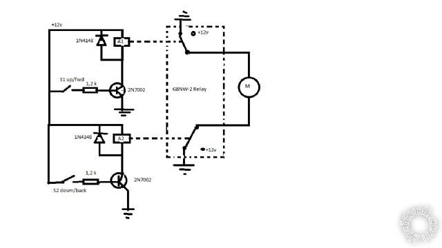
PS - I forgot - use 1N4004 (etc) diodes rather than 1N4148 which are signal diodes rather than power diodes.
.....................
LOL! I was thinking why use a transistor... What's this ruddy 2N7000 anyway....
Oh - it's an N-ch mosfet. (Yay!)
But it is only a low current device.
I usually take a one-size fits all approach - namely 60A-70A MOSFETs that can be obtained for ~$2.
They have lower on resistance as well. (2N7002 is ~5 Ohms!)
And being FETs, there is still negligible gate current.
(Unlike transistors - eg, a 2N3055 has a gain of ~20, hence for 10A you need a base (gate) current of 10A/20 = 500mA which is too much for a 20mA joystick. FETs require nA or uA.)
I suggest a resistor from the gate to GND to ensure the FET turns off in case of stray capacitance etc.
And the gate resistor (1.2k shown) can usually be anything - they are usually to protect the supplier of the gate "voltage" (joystick, or (NE555) PWM circuits etc). So assume 20V/20mA = 1k or larger. 1.2k is cool. But could be 10k or 100k etc.
Gate-GND resistors are usually (up to) 1M. It's not critical, but it forms a voltage divider with the Gate resistor ((1.2k).
Make it ~10 (or more) times the values of the gate resistor hence you "drop" les than 1/10th the gate's voltage. (No problem - usually 5V drain voltage (Vgs? or is it Vgd?) is enough for a full turn on, and we have 12V to play with.)
So if Rg = 1.2k, the Rgs should be 12k, or 100k etc.
(If Rg = 10k, then Rgs = 100k or 1M etc.) (If not Rgs, I mean fro the gate to GND for an N-ch FET. I think??)
I like FETs 'cos there are no base-current and "gain" issues.
You can actually connect the FET's gate straight to 12V to turn it on - no resistor is needed - it is a high-impedance input. You can't do that with a transistor!
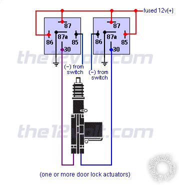
BTW - I too think +12V switching is easier. Not that P-ch FETs are difficult to come by, but there can be complications. (I've forgotten all that "high-side" switching stuff.)
FYI - re Sweden's backside (I like Göteborg's humör!) - I didn't write anything other than the truth!!
The backside "begged to differ" about my comment/s regarding a series of 3 or 4 LEDs (to be powered from a 555 PWM circuit).
Baksidan was under the impression that resistors were needed to prevent thermal runaway; that a runaway string would "rob current" for other parallel strings; that LEDs would NOT tolerate more than their "rated" 20mA; and that you "have to" put capacitors on PWM outputs to
filter the voltage!
I think he finally figured out that he didn't understand circuit analysis, Ohms Law, spec sheets, and the principles of PWM. The datasheet he provided for the 20mA (whatever) LEDs clearly showed those LEDs could tolerate 150mA or thereabout (with appropriate duty cycle!).
He thought I had an attitude problem.... But it was he that later deleted all his incriminating posts. Priceless! (Bad luck for him however - the original now hangs in some
Hall Of Fame somewhere.)
And this month's SiliconChip magazine features a project with a LED display using all the features I described to him - resistorless 2V LEDs off a higher supply (5V?) with peak currents of ~100mA instead of their "rated" 20mA. FIGJAM!
I wonder if he still adds capacitors to PWM outputs?
[ FYI - PWM - Pulse Width Modulation - a method of "chopping" the current to a circuit hence enabling dimming or speed control... essentially varying the power but keeping the same
operational voltage. Used for LEDs because changing the voltage doesn't work well - instead you keep its voltage constant but turn it off quickly at different "duty cycles" to vary the power (current) from 0% to 100%. Works for fluoro lights too. ]


 Printable version


