the12volt.com spacer
icon

2 potentiometers, one circuit


Post ReplyPost New Topic
< Prev Topic Next Topic >
oldspark 
Gold - Posts: 4,913
Gold spacespace
Joined: November 03, 2008
Location: Australia
Posted: August 22, 2010 at 6:57 PM / IP Logged  
FYI - Without further circuit analysis, I figure a 3.3k between green & yellow, else a 5.6k between yellow & orange (to change the alarm from 6500RPM to ~ 3,000RPM).
micrors4racer 
Copper - Posts: 88
Copper spacespace
Joined: August 18, 2009
Posted: August 22, 2010 at 7:24 PM / IP Logged  
Oh another question since this circuit used to be a tach, it has a shiftlight output. How would I connect that to my alarm LED? My alarm led is very visible and I do not want to add an unsightly shiftlight in my interior so I was hoping to make the LED dual purpose.
i am an idiot 
Platinum - Posts: 13,670
Platinum spaceThis member consistently provides reliable informationspace
Joined: September 21, 2006
Location: Louisiana, United States
Posted: August 22, 2010 at 9:15 PM / IP Logged  
You need to get to the 2 wires of the LED, and if you can put the alarm in valet mode to make the LED illuminate steadily, do that and check the DC voltage across the 2 wires.   Then with the LED turned off, I need to know if there is any voltage on either of the wires, using the vehicles chassis as a ground reference for your meter.
micrors4racer 
Copper - Posts: 88
Copper spacespace
Joined: August 18, 2009
Posted: August 23, 2010 at 6:02 AM / IP Logged  
The device works as intended with the 2 pots installed thanks!
The voltage for the led with my ground probe on a chassis ground (key slot) is 2.8v for the red wire and 00.01v for the black one. When the LED is off it is 0v for both.
i am an idiot 
Platinum - Posts: 13,670
Platinum spaceThis member consistently provides reliable informationspace
Joined: September 21, 2006
Location: Louisiana, United States
Posted: August 23, 2010 at 8:07 AM / IP Logged  

Set the meter to ohmns and check the resistance from each wire to chassis ground.  If the ground wire of the LED is common with ground under both of the previous conditions, it will be possible with a single relay and a resistor. 

I also need to know if the shift light is a 12 volt bulb?  Do you have any idea of the current capacity of the shift light output?  A standard Basch/Tyco relay will draw 160MilliAmps.

micrors4racer 
Copper - Posts: 88
Copper spacespace
Joined: August 18, 2009
Posted: August 24, 2010 at 8:31 PM / IP Logged  
With the LED on:
Red wire 1     . thats what my multimeter says
Black wire 00.6 - 00.9 fluctuates when i move the probe around
With LED off
Red wire 00.06
Black wire 00.2
I probed the 2 pin shiftlight plug and it reads 14v when the car is on. The bulb it uses is a normal incandescent bulb. Both pins read 14v and one drops to 10v when im hitting the limiter so does that mean its ground pulled? My limiting relay is hooked up to this shiftlight output which ground out the ignitor coil on and off hence limiting the rpms if you wanted to know how it works.
i am an idiot 
Platinum - Posts: 13,670
Platinum spaceThis member consistently provides reliable informationspace
Joined: September 21, 2006
Location: Louisiana, United States
Posted: August 24, 2010 at 9:08 PM / IP Logged  

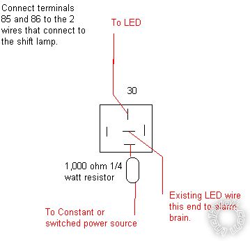
Cut the red wire between the LED and the brain.  Insert this relay.

2 potentiometers, one circuit - Page 4 -- posted image.

Text on the right reads: Existing LED wire, this end to alarm brain.  Install a diode across the coil of the relay.  Banded end of the diode on the positive wire.  Non banded end on the wire that goes closer to ground when the lamp illuminates.

micrors4racer 
Copper - Posts: 88
Copper spacespace
Joined: August 18, 2009
Posted: August 24, 2010 at 9:35 PM / IP Logged  
Thanks I'll try it out. I don't need diodes to stop the 12v from going into the alarm brain or from the alarm brain to the shiftlight circuit? And when you mean existing LED wire do you mean the positive? Can I use a 1k ohm 1/2 watt resistor?
i am an idiot 
Platinum - Posts: 13,670
Platinum spaceThis member consistently provides reliable informationspace
Joined: September 21, 2006
Location: Louisiana, United States
Posted: August 24, 2010 at 9:56 PM / IP Logged  
The diode is only to protect your LED and your shift light output  from the backlash of the relay coil.  It will probably be OK without one, but in case you have not yet figured out, I really do not want any of your equipment to fail on my watch.  Yes a 1/2 watt resistor will be twice as relaiable than a 1/4 watt device.
micrors4racer 
Copper - Posts: 88
Copper spacespace
Joined: August 18, 2009
Posted: August 24, 2010 at 10:08 PM / IP Logged  
Yes I understood the function of the diode on the coil thanks for always coming up with safe diagrams. I will try this now. I hate reading color bands on resistors as I am color blind haha
Page of 5

  Printable version Printable version Post ReplyPost New Topic
You cannot post new topics in this forum
You cannot reply to topics in this forum
You cannot delete your posts in this forum
You cannot edit your posts in this forum
You cannot create polls in this forum
You cannot vote in polls in this forum

  •  
Search the12volt.com
Follow the12volt.com Follow the12volt.com on Facebook
Saturday, May 4, 2024 • Copyright © 1999-2024 the12volt.com, All Rights Reserved Privacy Policy & Use of Cookies
Disclaimer: *All information on this site ( the12volt.com ) is provided "as is" without any warranty of any kind, either expressed or implied, including but not limited to fitness for a particular use. Any user assumes the entire risk as to the accuracy and use of this information. Please verify all wire colors and diagrams before applying any information.

Secured by Sectigo
the12volt.com spacer
Support the12volt.com
Top
the12volt.com spacer