the12volt.com spacer
icon

single switch, multiple outputs


Post ReplyPost New Topic
< Prev Topic Next Topic >
blowndakrt 
Copper - Posts: 94
Copper spacespace
Joined: March 14, 2008
Location: Iowa, United States
Posted: September 22, 2010 at 1:03 PM / IP Logged  
oldspark wrote:
Sorry - I thought there was more coming....
So.... you will add a rocker switch.
In its neutral position (off), windows operate normally.
In one position (on1) the valves are selected (instead of windows).
In the opposite position (on2) the actuators are selected.
The "pulsing" required is down by the switch operator.   
As you have drawn it, the valves are easy.
A DPDT relay for each end (1 front, 1 rear) placed "between" the window motors and the valves.
Contacts #30 to the Window Control Box.
Contacts #87a (NC) to window motors.
Contacts #87 to valves.
Both relay #85s to GND.
Both relay #86s to the added rocker switch's "on1".    
The same should apply to the actuators (not that the window motors are shown with them).
Hence 4 DPDT relays.... ??
Not sure what you mean by the window motors are not shown with them.
I wasn't sure how to draw it up with everything all in one drawing since I wasn't sure how many relays it was gonna take. But I can change the drawing to reflect all the devices coming out of the window control module and just draw in a couple of boxes to simulate the relay pack.
I did the drawing up to show 3 different scenarios. All of these will be controlled by the same 2 rocker switches for the windows. It will just depend on which direction the latched rocker (3rd rocker pictured) will be in as to which set of pictures it will branch out from out of the window control module.
Here it is redrawn.
single switch, multiple outputs - Page 4 - Last Post -- posted image.
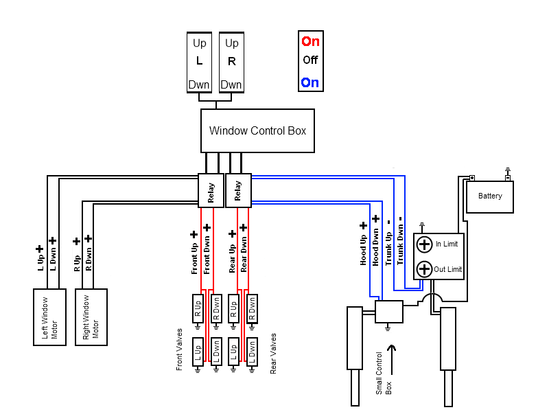
I realize it only shows 2 relays, but think of those 2 as the block of relays that will be needed.
The different colors show the direction of the rocker, and what the corresponding devices will be operating. Red On, will be going to the valve assembly, Black Off will be controlling the power windows, and Blue On will be going to the actuators.
Does this make more sense, or do I need to redraw it a different way? Just trying to be clear as to what I want the final outcome to be.
Thanks
Shawn
oldspark 
Gold - Posts: 4,913
Gold spacespace
Joined: November 03, 2008
Location: Australia
Posted: September 23, 2010 at 3:53 AM / IP Logged  
Ah! I thought the "upper" valves were window motors... d'oh!
Damned people and their interpretations...
Like how stupid would you be if you interpreted the "three scenarios" to be three time-shifted depiction from left to right?   
Of course you wouldn't know because you drew it in "real time" with the three "systems" from left to right!
I never would have expected such a logical or obvious layout.
Your are devious - you must know the sorts of diagrams I put up with.
NOTE! I am having fun. And it is a MY expense - NOT yours.   
(Just in case OPs think I am having a go at them as some poor OP from UAE did recently when a replier (also) LOL'd at his (IMO) humorous(?) depiction of "words to his contractors". Another non-existent problem that flamed into the bit bucket....)
Now having wasted another half a page....
And having reconsidered...
... and eaten egg....
GREAT! Even better!
Now, until I get to putting this diagramatically ....
Picture each of your "Relay" as being two relays - one under the other. Hence 2x2 relays = 4 total.
Each relay is DPDT - ie 2 pole changeover.
The top relay's NC contact #87a connects to the next (under) relay's input (#30), and its NO #87 goes to valves.
Hence if the top relay is energised the WCB (Window Control Box) output is diverted to the valves.
Otherwise....
The bottom relay is similarly connected with NO (Normally Open) #87 to the actuator/s, and its NC #87a to the windows.
Hence with the lower relay energised, the WCB output goes to the actuators.
If neither relay is actuated, the WCB output is connected to the windows (thru Normally Closed NC contacts #87a).
Now, 4 relays.
The upper 2 are for (say) valves.
The lower 2 are (thus) for actuators.
The 2 left-side relays are (say) for LHS window or front valves or bonnet... er, hood.
The 2 right-side relays are (this) for RHS window or rear valves or boot... er, trunk.
Obviously..... the assigning of left to front or rear is subject to your local convention else is arbitrary.
But the front valve should IMO be the same window-switch direction as front actuator hood/bonnet.
And we should all know that boots are up the rear! (That's another LOL...?)
And each relay has 2 poles - one for up, & one for down signals from the WCB.
Else 2 SPDT repays could be used with their coils (#85 & #86) in parallel.
So 4x DPDT else 8x SPDT relays as far as simple "switch decoding" and "up/down" to each of the targets goes.
I like it.
But it seems too simple. What a I missing.... (Forget "pulses" etc - that's separate.)
But this is an extension of my original diagram which uses hot switching instead of GND switching (and where relays negate the use of blocking diodes). (It also demonstrates how GND switching or Open-Collector outputs or "inverted logic" can greatly simplify circuitry.)   
And no diodes are required - unless coil-spike suppression is required, but it shouldn't be since the WCB control motors; maybe using relays itself?   
So Mr Smarty Boot, tell me where I've gone wrong this time! single switch, multiple outputs - Page 4 - Last Post -- posted image. single switch, multiple outputs - Page 4 - Last Post -- posted image.
Now, I'll get to modifying your diagram....
[Warning - I use "circuits" rather than "relay housing" depictions. That's because I want to easily trace the connections & operation. (Plus I rarely use Hella/Bosch type relays!)]
oldspark 
Gold - Posts: 4,913
Gold spacespace
Joined: November 03, 2008
Location: Australia
Posted: September 24, 2010 at 2:48 AM / IP Logged  
I had a choice of reality or drawing. I chose the latter.
How's below...? I drew it as 8 SPDT relays but it could could be 4 DPDT or 2 QPDT.
I thinks it's self explanatory. If not - maybe read my previous reply...?
Diagramatically I swapped Valve & Window positions for simpler route layout, and I crossed-over the horizontal lines for the Lids (hood/trunk)...
As mentioned earlier, the rocker could ground switch "hot" relay coils, or +12V switch them as shown. No big deal; whatever suits.
I haven't shown fuse(s) or spike-quenching diodes (across the coils - they are probably not needed).
Normal wiring drawing rules apply - crosses or crossovers are NEVER joints; any joints are show as T's (not that there are any). LOL - I miss the old dots, but really appreciate the new convention.
I didn't match line widths, nor colours...
And rather than confustigate with added solenoid connections, I just drew the one, but all "valve" solenoids common/joined; likewise all "Lid" solenoids. IR - it looks like two separate solenoids only.... (whether 2 lots of one, 2 or 4 relays).
Any problems just ask. But if you find the Doh! glaring mistake I'm bound to find in about 3 minutes - forget it - yesterday's chance was missed! (LOL!)
single switch, multiple outputs - Page 4 - Last Post -- posted image.
blowndakrt 
Copper - Posts: 94
Copper spacespace
Joined: March 14, 2008
Location: Iowa, United States
Posted: September 24, 2010 at 8:30 AM / IP Logged  
From your drawing, it looks as if the power from the latched rocker is going to the valves and the dotted line I am assuming it for the activation signal? Is that correct?
The valves are simply 2 wire feeds. You have your ground and then your 12 v push to make activation. Or is it just the way I am reading the diagram? Are what I am looking at as valves, actually relays?
Maybe I am over thinking this again and not fully following the diagram. I just want to make sure I am understanding the drawing before I ask any questions. No sense in asking if understanding the drawing as you drew it, would answer any questions I would be asking.
Thanks
Shawn
oldspark 
Gold - Posts: 4,913
Gold spacespace
Joined: November 03, 2008
Location: Australia
Posted: September 24, 2010 at 9:07 AM / IP Logged  
Hee hee. LOL. Ha ha!
My fault? I forgot to say the dashed lines represent the "electromagnetic solenoid-to-contact" interaction.
IE - a solenoid pulls in the contact it is dashed to.
(And - by convention, de-energised is "away" from the solenoid since solenoids pull contacts TOWARDS them. But, if shown arse-about, that is understood and accepted.)
LOL - to think I took the trouble to show solenoids IN-LINE with their contacts... (Often they are remote and don't even include "bent" or zig-zag lines to make it obvious which solenoid for which contact - they just label (say) S1 and then "1a" and "1b" for the contacts; and S(olenoid)2 will have c2a & c2b or (Contacts) 2a & 2b etc.)
I thought it would be obvious. It is so well understood in my circles... (whereas the12volt's "physical" drawings stuffs me/us up completely! Plus 10%.)
Hopefully this is now "as obvious" to you as your drawing "became obvious" to me...
Does this/that make sense?
I will now re-read your last reply.....
WARNING: I will soon enter a religious period of comatose worship. Hence I may soon be unavailable until released from care, or someone posts bail. (If worse than that - fear not - I WILL channel!)
I am currently well into my pre-consumpotive practice session for said observance!
blowndakrt 
Copper - Posts: 94
Copper spacespace
Joined: March 14, 2008
Location: Iowa, United States
Posted: September 24, 2010 at 9:28 AM / IP Logged  
Ok, I think I understand now.
So the 12v from the latched rocker will come into 85 with it in the first on position. 86 will be to ground. Output from the WCB will go to 87, and 87a will go to front valves. 30 will go down to the lower set of relays and connect to 87a, and 30 will go to window motor wires. 87 will go linear actuators. Then 85 will go to the 12v from the latched rocker in the second on position.
Is that correct? Or do I have 87 and 87a mixed up on the lower (second) set of relays.
Thanks
Shawn
oldspark 
Gold - Posts: 4,913
Gold spacespace
Joined: November 03, 2008
Location: Australia
Posted: September 24, 2010 at 9:53 AM / IP Logged  
Yeah - I think mixed...
But so am I.
Observing solenoid polarity convention (#85 & #86):
single switch, multiple outputs - Page 4 - Last Post -- posted image.
blowndakrt 
Copper - Posts: 94
Copper spacespace
Joined: March 14, 2008
Location: Iowa, United States
Posted: September 25, 2010 at 8:58 AM / IP Logged  
So your drawing is showing all relays in the NC position.
I think I understand now. I was just confused as your top relay config was mirror images of the lower ones, so I was reading it as 87 and 87a were switched.
But I see you did that for ease of drawing and to keep the drawing cleaner.
And I see that the positive side coming from the switch is going to go to 86 not 85. Question, does that matter? I have heard when it comes to 85 and 86 that it does not matter which is positive and which is ground. Is this true, or does swapping 85 and 86 cause the relay to be in the NO position at rest?
So every output going to the devices are positive outputs. So I can simply add another set of relays for the one device that needs a negative output.
Thanks
Shawn
oldspark 
Gold - Posts: 4,913
Gold spacespace
Joined: November 03, 2008
Location: Australia
Posted: September 25, 2010 at 11:10 AM / IP Logged  
85 & 86 do not matter UNLESS the relay has an internal diode to absorb/quench (negative) spikes from its coil, in which case 86 is +ve and 85 -ve.   
Hence the general convention of 86 > 85 voltage wise.
For negative switching - yes - insert as SPST (or DT) relay - ie, instead of existing 87 going to the target (eg, hood), it'll go to 86 of the new relay with that relay's 85 & 30 to GND and 87 to the target.
Page of 4

Sorry, you can NOT post a reply.
This topic is closed.

  Printable version Printable version Post ReplyPost New Topic
You cannot post new topics in this forum
You cannot reply to topics in this forum
You cannot delete your posts in this forum
You cannot edit your posts in this forum
You cannot create polls in this forum
You cannot vote in polls in this forum

  •  
Search the12volt.com
Follow the12volt.com Follow the12volt.com on Facebook
Thursday, May 16, 2024 • Copyright © 1999-2024 the12volt.com, All Rights Reserved Privacy Policy & Use of Cookies
Disclaimer: *All information on this site ( the12volt.com ) is provided "as is" without any warranty of any kind, either expressed or implied, including but not limited to fitness for a particular use. Any user assumes the entire risk as to the accuracy and use of this information. Please verify all wire colors and diagrams before applying any information.

Secured by Sectigo
the12volt.com spacer
Support the12volt.com
Top
the12volt.com spacer