issakar wrote:
| To think just a few weeks ago I couldn't even begin reading a wiring diagram... |
|
|
THAT is what makes it so worthwhile and rewarding!
That is what the12volt strives to do. Solving the problem is one thing, but to make people realise what they are capable of... (I think that's called edukashun. Or is it self-actualisation & -realisation?)
But enough of my young(
cough!) innocent (
cough cough!) naive idealistic rambling!
A bad ground? Oh yes - definitely.
The common and evil ground-gremlin is probably the most basic yet confusing, damaging and subversive
bug to exist in any electrical system!
[ Yes - it's true - Gremlins are really bugs! (Trust me...) ]
I did mention it - probably because I was lucky enough to remember the in-obvious obvious potential (pun intended - potential as in voltage).
And I suppose ~36 seconds would be enough for me to look back and check, but who has time for that?!
Check the voltages at FUEL TANK MODULE terminals 4 & 6 with POWER DISTRIBUTION CENTRE 5B shorted to 5C. They should near 0V. Perhaps 1V max (assuming the Fuel Pump is drawing its current).
BTW - I used the expert-TECH SPEAK you and now I are so familiar with. But let's keep the translation to ourselves!
The rest hereunder is optional reading...
A grounding in grounding:
Picture a ground as a resistor. It can be perfect - ie, zero resistance; bad can be from a fraction of an Ohm to many Ohms; or open-circuit (ie, infinite resistance/Ohms).
If open, the "thing" shouldn't (or won't) work, and all voltages
upstream should be "high" and the same.
[ Open means zero current means zero voltage
drop. Ohms Law: V=IR "
The voltage across a device equals its resistance times the current going through it. ]
If perfect, we don't care. The "ground" voltage drop will be zero. (V=IR; if I = 10A, then V = 10 x 0 = 0V because "perfect" is zero Ohms/Resistance.)
But in practice, everything has resistance, but ground and power resistance should be small enough to
minimise the voltage drops (which increase with increasing load/current).
Power grounds should me milli-Ohms if that.
EG - for 10A & 1mR, V=IR = 10A x 1mR - 10mV = 0.01V (or 10 x 0.001 = 0.01V).
NOTE - I am using "R" instead of the Ohm symbol Ω because I couldn't be bothered finding it... I mean, Ω can have problems in different fonts or applications, and since we don't understand foreign languages and R is on our keyboards anyway....
Where was I....?
Oh yeah, a 0.01V drop in a 12V system - bah! nothing, negligible!
But if the GND is 1/10th of an Ohm:
V = 10 x .1 = 1V. Hey - that's 1V in 12V - we are getting concerned.
Fit a 100A load or amp(lifier) to that... V = 100A x 0.1R = 10V. Now we do have a problem!
(In practice you won't get that current thru the circuit hence not that "ground drop" - the
total circuit resistance limits the current. But that's for another time - let's keep it simple (
coughs again!).
The point is bad grounds result in UNDER-current and voltage - the
load probably won't work - ie amplifier, fuel pump etc.
[ In some situations, bad grounds can be damaging. Alternators can overcharge and cook batteries; electronics can fry due to inter-ground currents (across ground voltage drops) etc. ]
Hence the "Big 3" etc etc.
Trust me, I've tried to get rid of GNDs and electricity
return paths but the things just refuse to work!
Selfish $#$@s!! - one "feed" isn't enough -
they want TWO! Both the "feed" and the "return".
They must be of that Greenie recycler clan! (Good!!)
(The above was attempted humour.)
Rats! I've already explained the effect of a
bad ground in the above example. Never a perfect ground eh? But good enough depends on the circuit....
Oh well, that gives me time & space to say that IMO, get a few "basics" and abilities simply accumulate...
The main basics include being able to understand wiring diagrams - including crappy ones!
[Break them down; isolate or do one section or circuit or wire at a time. A pencil or colored marker(s) can be godsends - especially on (multiple!) diagram copies!]
Then there is the basic understanding of electricity (that's where the water analogy is excellent!) and that usually involves an understanding of the simplicity of Ohms Law. (The pressure drop along a pipe is proportional to it's size and the amount of water going through it. IE - as size/diameter decreases its resistance increases, and more flow quantity means higher friction and turbulence - ie, higher resistance.)
[Water currents and electrical current - coincidence? I think not! (LOL)]
Most people "understand" Ohms Law - they just don't realise it.
Mind you, applying to a circuit can be tricky (I still get caught!), but you learn the tricks with experience. (Which in retrospect are so damned obvious, but....!!)
It is yet again breaking down in to basics - currents THROUGH a device and its "string" OR the voltage ACROSS various devices or strings (and their resistance) to work out total resistance or current. On part at a time...
Alas, ramble.
But I am curious if your last "could it be ground?" was a
self realisation, or a subtle re-read (and thus flagged or realised).
If the former, I am impressed.
Though I'm still impressed with the latter - after all, you prompted me, I didn't remind you.
And better still, it wasn't a question AFTER buying a new relay, or pump, or battery, or vehicle!
But really, though I suspect it was
self realisation, who cares?
I think your "
... couldn't even begin reading a wiring diagram, lol." (ie, LOL) says it all!
Good luck - not that luck seems relevant in your case.


 Topic Closed)


 wiring diagram


 [ POST EDIT - I have updated with the above diagram. I hope it makes sense, and isn't wrong! ]
The rest hereunder is trivial...
"AUTOMATIC SHUT DOWN RELAY OUTPUT" (FUEL TANK MODULE C327) is a crappy name for "the Fuel Pump".
And "FUEL TANK MODULE"' is a crappy name for a "Fuel Tank".
The former is NOT an output and the latter is NOT a module (IMHO).
"From (or To) AUTOMATIC SHUT DOWN RELAY OUTPUT" and "FUEL TANK Assembly" may be acceptable. But I'd prefer "From FUEL PUMP RELAY" or better still, simply "Fuel Pump" and "Fuel Tank". It's a simple wiring diagram!
(Per chance, did Microsoft write their documentation?)
Personal Conclusion - I should just analyze on screen instead of thinking I always need to print diagrams and legends. Only one "block" in the relay guide was relevant (d'oh!) and the wiring diagram was easy (d'oh #2!)
[ POST EDIT - I have updated with the above diagram. I hope it makes sense, and isn't wrong! ]
The rest hereunder is trivial...
"AUTOMATIC SHUT DOWN RELAY OUTPUT" (FUEL TANK MODULE C327) is a crappy name for "the Fuel Pump".
And "FUEL TANK MODULE"' is a crappy name for a "Fuel Tank".
The former is NOT an output and the latter is NOT a module (IMHO).
"From (or To) AUTOMATIC SHUT DOWN RELAY OUTPUT" and "FUEL TANK Assembly" may be acceptable. But I'd prefer "From FUEL PUMP RELAY" or better still, simply "Fuel Pump" and "Fuel Tank". It's a simple wiring diagram!
(Per chance, did Microsoft write their documentation?)
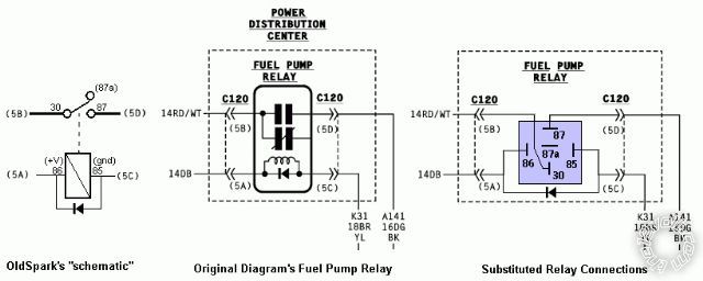
Personal Conclusion - I should just analyze on screen instead of thinking I always need to print diagrams and legends. Only one "block" in the relay guide was relevant (d'oh!) and the wiring diagram was easy (d'oh #2!)  FYI - the circuit is "typical".
The fuel pump is powered from the (fused) battery (#30, 5B) thru the relay (#87, 5D).
It's a "hot" coil - ie, Ignition +12V to #86/5A - which is grounded (#85/5C) by the C19 FUEL PUMP RELAY CONTROL (POWERTRAIN CONTROL MODULE; C175) to turn the pump on. (Probably an "Open Collector" transistor; it "floats" when off and shorts (connects) to GND when on. That is typical for digital EMS/ECU etc outputs.)
FYI - the circuit is "typical".
The fuel pump is powered from the (fused) battery (#30, 5B) thru the relay (#87, 5D).
It's a "hot" coil - ie, Ignition +12V to #86/5A - which is grounded (#85/5C) by the C19 FUEL PUMP RELAY CONTROL (POWERTRAIN CONTROL MODULE; C175) to turn the pump on. (Probably an "Open Collector" transistor; it "floats" when off and shorts (connects) to GND when on. That is typical for digital EMS/ECU etc outputs.) Printable version


