the12volt.com spacer
icon

ford focus door unlock stopped working


Post ReplyPost New Topic
< Prev Topic Next Topic >
howie ll 
Pot Metal - Posts: 16,466
Pot Metal spacespace
Joined: January 09, 2007
Location: United Kingdom
Posted: October 09, 2010 at 5:14 PM / IP Logged  
use your key to verify which of the white or yellow ires is lock or unlock then tell me the six colours of your alarm lock wires.
mrsinger 
Member - Posts: 23
Member spacespace
Joined: April 07, 2009
Location: Lithuania
Posted: October 10, 2010 at 7:45 AM / IP Logged  
ok, how many motor wires there should be?
howie ll 
Pot Metal - Posts: 16,466
Pot Metal spacespace
Joined: January 09, 2007
Location: United Kingdom
Posted: October 10, 2010 at 8:39 AM / IP Logged  
2 and they should be WHITE/ black and yellow/black, I can see them in the photo.
mrsinger 
Member - Posts: 23
Member spacespace
Joined: April 07, 2009
Location: Lithuania
Posted: October 10, 2010 at 11:26 AM / IP Logged  
OK, I've checked wires, and the first 3 on the green plug are: yellow/black which gives impuls more then 10V on lock and 0.2V on unlock, and the next two are WHITE/ black wires, which act the same - 0.2V on lock and more then 10V on unlock. I'm a bit confused, that it's not 2 but three wires, and two of the three acts identically.
As of alarm lock wires, sure I can write down the colors, but not sure if it's important, because it's quite simple, it's 2 identical relays connected - one contact is connected short on idle to another, and when locking it connects to 3rd contact, the other 3 contacts are working the same way only on unlocking. I could draw some diagram how it's done if it would do any help.
howie ll 
Pot Metal - Posts: 16,466
Pot Metal spacespace
Joined: January 09, 2007
Location: United Kingdom
Posted: October 10, 2010 at 11:38 AM / IP Logged  
OK, the yellow/black and either WHITE/ black, it shouldn't matter.
I'd be grateful if you could print the wires and their colours and what the alarm says or else the make of alarm.
They should be listed as follows:
Lock common.
Lock normally closed (NC).
Lock normally open (NO).
Same for unlock.
mrsinger 
Member - Posts: 23
Member spacespace
Joined: April 07, 2009
Location: Lithuania
Posted: October 10, 2010 at 12:29 PM / IP Logged  
Ok, I get it, these are the wires of alarm:
black: lock normally closed (NC)
green: lock common
pink: lock normally open (NO)
white: unlock normally closed (NC)
violet: unlock common
orange: unlock normally open (NO)
howie ll 
Pot Metal - Posts: 16,466
Pot Metal spacespace
Joined: January 09, 2007
Location: United Kingdom
Posted: October 10, 2010 at 1:24 PM / IP Logged  
OK;
cut car's yellow/black,
black to GEM box side, green to car side,
pink and orange shared 15amp (20amp if 4 door) fused to 12V+ constant.
cut BOTH WHITE/ blacks. The GEM box side of one, unused.
Then, white to remaining GEM box side.
Violet to BOTH remaining car side WHITE/ blacks.
OR connect to one, then branch out to a relay from the violet terminal 86, 85 to ground.
Unused GRM box side to 87a, then from the fused side of the pink and orange connect to 87, join 30 to the other WHITE/ black.
Also diode across 85 and 86, type 1N4004, band towards 86 (solder to the base of the pins). This method is safer, doesn't interfere with the car's electrics.
This should restore lock control and should still give you key or factory remote control .
mrsinger 
Member - Posts: 23
Member spacespace
Joined: April 07, 2009
Location: Lithuania
Posted: October 11, 2010 at 2:36 AM / IP Logged  
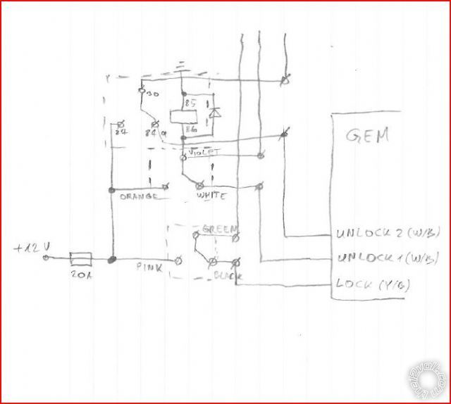
ok, thanks for the advice! I've made some drawing to see if I understand it correctly. Is it correct? I'm nor sure about diode polarity. Also I wonder, what if factory remote control will be used, won't it switch relay I'll add?
And if unlocking the way it's connected now works ok, maybe it would be enough just to change wiring for locking, only these three wires - green, black and pink? ford focus door unlock stopped working - Page 2 -- posted image.
howie ll 
Pot Metal - Posts: 16,466
Pot Metal spacespace
Joined: January 09, 2007
Location: United Kingdom
Posted: October 11, 2010 at 2:50 AM / IP Logged  
Yes, just use the lock side on the yellow/black.
The way it's wired won't affect the factory wiring.
mrsinger 
Member - Posts: 23
Member spacespace
Joined: April 07, 2009
Location: Lithuania
Posted: October 12, 2010 at 11:11 AM / IP Logged  
well, I've tried to connect lock part as you've suggested, leaving unlock the way it was, and now lock/unlock works perfectly! :) thanks you a lot, you've saved me many hours which I'd spend looking for solution :) Thanks! :)
Page of 3

  Printable version Printable version Post ReplyPost New Topic
You cannot post new topics in this forum
You cannot reply to topics in this forum
You cannot delete your posts in this forum
You cannot edit your posts in this forum
You cannot create polls in this forum
You cannot vote in polls in this forum

  •  
Search the12volt.com
Follow the12volt.com Follow the12volt.com on Facebook
Monday, April 29, 2024 • Copyright © 1999-2024 the12volt.com, All Rights Reserved Privacy Policy & Use of Cookies
Disclaimer: *All information on this site ( the12volt.com ) is provided "as is" without any warranty of any kind, either expressed or implied, including but not limited to fitness for a particular use. Any user assumes the entire risk as to the accuracy and use of this information. Please verify all wire colors and diagrams before applying any information.

Secured by Sectigo
the12volt.com spacer
Support the12volt.com
Top
the12volt.com spacer