the12volt.com spacer
icon

2003 ram manual remote start ultra start


Post ReplyPost New Topic
< Prev Topic Next Topic >
a.beam.reach 
Member - Posts: 19
Member spacespace
Joined: November 09, 2010
Posted: November 09, 2010 at 9:54 PM / IP Logged  
I have successfully done a remote start install once before on an automatic vehicle but I have four questions on installing an Ultra Start U1271M on my 2003 Dodge Ram with Manual transmission.
The best vehicle notes I have found are at: Bulldog Security's Website.
1st Question: My remote starter claims that it has 5 'on-board' relays but there is really very little info more about them. The included directions show that the unlock and lock outputs are both a negative 250ma (though the instructions found on their website shows they are both a negative 500ma). I understand that on my vehicle the system is a single wire control and I understand that I need to wire 330 and 820 ohm resistors . . ..   What I don't understand is whether my unit is sending the appropriate 'relayed' signal or do I need to wire relays in? Here are the options on bulldogs site
2nd Question: Because it is a manual transmission. . . . for the 'reservation' mode to work properly the door triggers need to be wired. Bulldog indicates for an alarm installation you could use the dome light wire in the 'A' pillar for this purpose as shown here. My application is not an alarm but it seems that by using this wire I could avoid running a trigger wire with diodes to all the doors. . . . am I correct?
3rd Question: The instructions for my remote starter indicates that there are 4 types of clutch switches and thus different ways to bypass the switch. I can not find any information on what type of switch I have and how to bypass it. Please tell me how to bypass my switch. If relays are required please be specific on the setup that is required.
Last Question: On the last install I did. . . .   I just stripped a portion of the wire that I was 'tapping' into and wrapped the two or three applicable wires together and taped (electric) around them. . . . this worked for the 5 years I had the vehicle. What is the preferred method? Are their quick connectors that work well?
Thanks in advance for any help you can offer.
KarTuneMan 
Platinum - Posts: 7,056
Platinum spaceThis member has made a donation to the12volt.com. Click here for more info.spaceThis member consistently provides reliable informationspace
Joined: December 14, 2004
Location: Isle Of Man
Posted: November 09, 2010 at 10:49 PM / IP Logged  

question 1 YES you need relays. you can build your relays like the top ones in your diagram.

question 2 YES, you are correct.

question 3 find a brown and yellow at/on the clutch switch. This need a "ground while running" Or a negative start pulse,  to bypass the clutch.

final question get a soldering iron.

a.beam.reach 
Member - Posts: 19
Member spacespace
Joined: November 09, 2010
Posted: November 10, 2010 at 12:20 AM / IP Logged  
Thank you KarTuneMan!
Question 1: Ok . . . I'll add the relays and wire them as shown below:
2003 ram manual remote start ultra start -- posted image.
For my edification. . . . I know relays can serve many purposes. . . In this case what are the relays doing?
Question 2: Thanks. . . . that will save a little work.
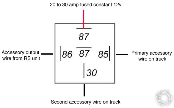
Question 3: On the remote starter I have a 30amp Select Output Wire - Selectable output for 2nd Ign, acc or starter. 2003 ram manual remote start ultra start -- posted image.
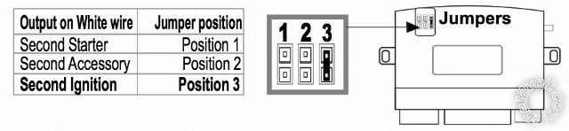
Is this the wire I would use and reverse the polarity to the brown and yellow wire at/on the clutch switch? What would I set the 'jumper' to? Ignition or starter?
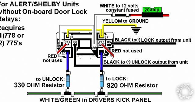
Would I then reverse the polarity with a relay and wire it as shown below?
2003 ram manual remote start ultra start -- posted image.
Do I need to first test the brown and yellow wire? If so, what do I test for?
Question 4: I have a soldering iron. . . . . what type of solder should I use?
Thanks again for your help. I am one of those that while I like to save a buck. . . . I really like the challenge and experience of learning something new!
kreg357 
Platinum - Posts: 7,783
Platinum spaceThis member has made a donation to the12volt.com. Click here for more info.spaceThis member has been recognized as an authority in Electrical Theory. Click here for more info.spaceThis member has been recognized as an authority in Mobile Security and Convenience. Click here for more info.spacespace
Joined: January 30, 2009
Location: Pennsylvania, United States
Posted: November 10, 2010 at 9:33 AM / IP Logged  

1.)  Current Draw.  Most remote straters without door lock relays can handle a limited current on their lock / unlock outputs.

3.) Your truck has two Ignition wires and Two Accessory wires.  Set the U1271 jumper for Ignition2 and use the White wire for the trunks Ignition2 wire.  That will leave you with the trucks ACC2 wire to power.  An extra 30/40A SPDT Relay and a 20 Amp fuse will be needed for that.  Althought Bulldog Security suggests connecting the remote starts ACC output to both, that's not usually a good idea.  Not sure on the clutch bypass, usually a  relay setup controlled by GRW or Starter will work.  If yours is a low current (-) as KarTuneMan suggests then GWR directly to the correct wire is all you need.  If you are using GWR for your bypass too, diode isolate the connections.

4.) 63 / 37 is best but 60 /40 is more common / available.  A solder with a "no clean" flux is preffered. 

This is a good one : Kester 245 No Clean Wire Solder 63/37 .031" 1 lb. Spool

Soldering is fun!
a.beam.reach 
Member - Posts: 19
Member spacespace
Joined: November 09, 2010
Posted: November 10, 2010 at 3:23 PM / IP Logged  
Thank you kreg357!-
I can't believe I missed the fact that I needed both of the ignition outputs for my truck. I am glad that I am spending so much time wrapping mind around the project before actually diving in. Now I'll just need to figure out how to wire in the extra 30/40A SPDT Relay and a 20 Amp fuse to power the ACC2. Is the below drawing correct?
2003 ram manual remote start ultra start -- posted image.
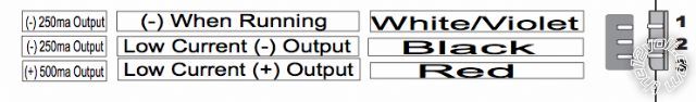
I don't need bypass (black key) so my - while running wire is unused. How can I confirm low current (-) as KarTuneMan suggests? I have an analog amp meter. .. .   just need to know what to do and what to test for. Assuming it is low current. . . Would I just use the - while running wire as shown below and connect it to the brown and yellow wire at/on the clutch switch?
2003 ram manual remote start ultra start -- posted image.
Thanks for your help.
kreg357 
Platinum - Posts: 7,783
Platinum spaceThis member has made a donation to the12volt.com. Click here for more info.spaceThis member has been recognized as an authority in Electrical Theory. Click here for more info.spaceThis member has been recognized as an authority in Mobile Security and Convenience. Click here for more info.spacespace
Joined: January 30, 2009
Location: Pennsylvania, United States
Posted: November 10, 2010 at 4:52 PM / IP Logged  

If you are going to use just only relay for the ACC2 circuit, your drawing is almost correct.

Pin 87 to +12v constant thru appropriate fuse.

Pin 86 to U1271 ACC1 output Green ( that is also connected to the trucks ACC1 wire at ignition harness).
Pin 30 to trucks ACC2 wire at ignition switch harness.
Pin 85 to U1271 GWR WHITE/ Violet wire with inline 1N4001 diode, band towards U1271.
Pin 87a is not used and should be insulated.

This relay will be actuated whenever the ACC1 ciruit is on (+) AND the U1271 GWR signal (-) is active in a remote start.  The diode is to keep the circuit islolated because you will also be connecting GWR to the clutch depressed wire for clutch bypass during remote start.  An inline diode with the band towards the U1271 will be necessary in the GWR branch to the clutch wire also.

Below is the diagram I have for the U1271s' bypass connector where you will get the GWR signal.  

Ground While Running Output (-)250ma        WHITE/ VIOLET

Ground Output (-)250ma                                    BLACK
12Volt Output (+)250ma                                     RED

I believe most newer Ultra Start units have circuit overload protection for their low current outputs so you can try it directly wired without harm to the U1271.  If you don't want to chance it, a 10A SPDT relay can be used as follows:

Relay Pin 85 to GWR with inline diode

Relay Pin 86 to +12v constant thru 5A fuse
Relay Pin 87 to Chassis Ground
Relay Pin 30 to Clutch wire

Soldering is fun!
kohara73 
Copper - Posts: 192
Copper spacespace
Joined: December 08, 2005
Location: Canada
Posted: November 10, 2010 at 5:03 PM / IP Logged  
I just thought I'd add a comment regarding question 2. Make sure your truck does not turn the interior lights on when you turn it off. This will kill your reservation mode. My car with a manual trans does this. When I get out of it, keys and remote in hand, car running, it turn interior lights on when I shut it down with remote. If your truck does the same thing, you will have to use the door triggers.
Keith
a.beam.reach 
Member - Posts: 19
Member spacespace
Joined: November 09, 2010
Posted: November 10, 2010 at 5:21 PM / IP Logged  
Thank you kreg357 and kohara73!
I think I am ready to tackle this now.
kohara73. . . . My light does not come on when I turn the car off but it does come on when you open the doors and stays on for about 30 seconds after I shut / lock the doors. Does this mean that I would need to keep the truck running until the lights turn out in order to keep the RS in reservation mode? If so . . . I might just attach to the driver door trigger. I am not really worried about someone entering from the other three doors and putting the car into gear.
kohara73 
Copper - Posts: 192
Copper spacespace
Joined: December 08, 2005
Location: Canada
Posted: November 10, 2010 at 5:31 PM / IP Logged  
Try this...Sit in the truck with it running. Open the door, close the the door. The dome light delay may not be present with it running. Then turn truck off. Then press lock button on door. You have just done what your reservation mode will do. If the dome goes out as soon as the door is closed and doesn't come on again when the truck is turned off and locked, you should be OK to use the dome light as your door trigger.
Keith
kreg357 
Platinum - Posts: 7,783
Platinum spaceThis member has made a donation to the12volt.com. Click here for more info.spaceThis member has been recognized as an authority in Electrical Theory. Click here for more info.spaceThis member has been recognized as an authority in Mobile Security and Convenience. Click here for more info.spacespace
Joined: January 30, 2009
Location: Pennsylvania, United States
Posted: November 10, 2010 at 5:46 PM / IP Logged  

Although it's 4 more diodes and two long wires over to the Passenger Kick Panel, if the Dome Light wire does not allow easy entry into "Reservation Mode", I would wire all four doors status'.  A 5,000 pound diesel truck is a hard thing to stop...

NOTE *3 the DRIVERS DOOR is a TAN (-), the DRIVERS REAR DOOR is a TAN/ORANGE (-) or a PURPLE / ORANGE (-), these wires are in the DRIVERS KICK PANEL. The PASSENGE DOOR is a TAN/RED (-) and the PASSENGER REAR DOOR is a TAN / YELLOW (-), these wires are in the PASSENGER KICK PANEL. When connecting to an ALARM SYSTEM, use all 4 DOOR TRIGGER wires and DIODE ISOLATE. to connect, See DIAGRAM

Soldering is fun!
Page of 2

  Printable version Printable version Post ReplyPost New Topic
You cannot post new topics in this forum
You cannot reply to topics in this forum
You cannot delete your posts in this forum
You cannot edit your posts in this forum
You cannot create polls in this forum
You cannot vote in polls in this forum

  •  
Search the12volt.com
Follow the12volt.com Follow the12volt.com on Facebook
Tuesday, April 23, 2024 • Copyright © 1999-2024 the12volt.com, All Rights Reserved Privacy Policy & Use of Cookies
Disclaimer: *All information on this site ( the12volt.com ) is provided "as is" without any warranty of any kind, either expressed or implied, including but not limited to fitness for a particular use. Any user assumes the entire risk as to the accuracy and use of this information. Please verify all wire colors and diagrams before applying any information.

Secured by Sectigo
the12volt.com spacer
Support the12volt.com
Top
the12volt.com spacer