the12volt.com spacer
icon

2002 explorer sport trac hu


Post ReplyPost New Topic
< Prev Topic Next Topic >
Ween 
Platinum - Posts: 1,366
Platinum spacespace
Joined: August 01, 2004
Location: Illinois, United States
Posted: January 04, 2011 at 6:12 PM / IP Logged  
yes, but as i said, you may have to remove all terminals from the housing and then replace them into their respective positions. an additional thought, are the terminals on the 8-pin connector laid out 2 x 4 grid style (90deg) or is there a slight stagger to them? i believe metra has a harness that is of the staggered variety, no rcas just wires. you could solder rca ends on those.
mark
dosman 
Member - Posts: 10
Member spacespace
Joined: January 03, 2011
Location: Alberta, Canada
Posted: January 04, 2011 at 11:20 PM / IP Logged  
That will probably be my best bet. I'm starting to get a better picture of this now.
So I would have to get 3 female rca on the 8 pin amp harness in there correct pin orientation.
pin 1 ...RED / black sub- ----------------RCA- to amp sub input
pin 2 ...BROWN / orange sub+---------------RCA+
pin 3 ...light GREEN / WHITE lf- -----------------RCA-LF SPKR AMP input
pin 4 ...dark GREEN/ violet remote gos to Blue/White AMP REM on hu ?
pin 5 ...dark blue / YELLOW lf+ -----------------RCA+ LF SPKR AMP input
pin 6 ...light GREEN/ violet rf+ -----RCA RF+ SPKR AMP input
pin 7 ...light GREEN/ orange rf- -----RCA RF- SPKR AMP input
pin 8 ...not used
How do you read the pins is there a standard? Because when you say pin position 1 it could be read top right to left then bottom right to left? It also depends how your holding it...
Sorry to ask dumb questions
Here's what the Metra 70-5519 looks like.
8 Pin ford Amp
2002 explorer sport trac hu - Page 2 -- posted image.2002 explorer sport trac hu - Page 2 -- posted image.
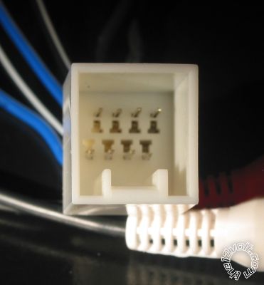
16 pin harness Missing two do you know the pin number that are missing?
2002 explorer sport trac hu - Page 2 -- posted image.
Thanks Ween I owe ya a beer....
Dosman
Ween 
Platinum - Posts: 1,366
Platinum spacespace
Joined: August 01, 2004
Location: Illinois, United States
Posted: January 05, 2011 at 6:32 AM / IP Logged  
the terminals look staggered on the 8-pin. mate the connector to the vehicle. see if the RED / black lines up with the shield of the rca, that will be your pin 1, next to it in a row would be 2, 3 and 4.
5 through 8 follow on the next row beneath...1 opposite 5 etc.
the missing terminals on the 16-pin are 3 and 4...shouldn't be needed on your aftermarket head unit.
dosman 
Member - Posts: 10
Member spacespace
Joined: January 03, 2011
Location: Alberta, Canada
Posted: January 05, 2011 at 9:39 AM / IP Logged  

The search gods were good to me last night I noticed on the 2003 Ranger wiring diagram that the part number for the connector was C290a

and when I did a search.

http://ww2.justanswer.com/uploads/paynlessauto/2009-09-28_013229_pioneerconnector.pdf

I think this will be all I need.

I will wait for it to warm up a bit and then I will head out to the garage. It's cold here right now...LOL

Again thanks for your help.

Dosman
Ween 
Platinum - Posts: 1,366
Platinum spacespace
Joined: August 01, 2004
Location: Illinois, United States
Posted: January 05, 2011 at 12:17 PM / IP Logged  

if you can get the 290b connector also, that will be the amplifier input harness, at the rear of the radio.

m

dosman 
Member - Posts: 10
Member spacespace
Joined: January 03, 2011
Location: Alberta, Canada
Posted: January 05, 2011 at 2:47 PM / IP Logged  

Plug C290b It's on page 2 . as you stated before

pin 1 ...RED / black sub- ----------------RCA- to amp sub input

pin 2 ...BROWN / orange sub+---------------RCA+

Do you know why Pin 1 is listed as RX signal and Pin 2 TX signal.

Or is that just Fords way of confusing things.

2002 explorer sport trac hu - Page 2 -- posted image.

Thanks

Dosman
Ween 
Platinum - Posts: 1,366
Platinum spacespace
Joined: August 01, 2004
Location: Illinois, United States
Posted: January 05, 2011 at 7:14 PM / IP Logged  
i think it's ford confusing things...look at how the connector at the amplifier is labeled, circuit numbers are the same, descriptions different.
dosman 
Member - Posts: 10
Member spacespace
Joined: January 03, 2011
Location: Alberta, Canada
Posted: January 06, 2011 at 12:26 AM / IP Logged  
Done, pulled out and dusted off my soldering iron and turned my C290b 8 Pin 2x RCA into 3X RCA. Used my multimeter to test polarity and every thing is checked and looks ready to go.
I used a dental pick and small screw driver to push the pins out,that was no easy task. found an RCA plug and soldered them on.
so it looks good to go.
It gets dark here before I get home from work so I will wait till the weekend to give it a test. I will let you know how it go's
Again thanks for your help.
Dosman
dosman 
Member - Posts: 10
Member spacespace
Joined: January 03, 2011
Location: Alberta, Canada
Posted: January 10, 2011 at 12:14 AM / IP Logged  
Success, went out and plugged it in and it was perfect.
It sound much better then the factory hu.
Thanks for your help
Dosman
kaczman 
Member - Posts: 4
Member spacespace
Joined: September 30, 2011
Location: Ohio, United States
Posted: September 30, 2011 at 10:57 AM / IP Logged  
Wow, I hate to resurrect this thread from the dead, but Im having the same problem. I bought the 5701 harness, which I think is bad. Looks like I need the 5519. The problem I was having was that my drivers front speaker wouldnt turn on when everything was connected. ANy ideas?
Page of 2

Sorry, you can NOT post a reply.
This topic is closed.

  Printable version Printable version Post ReplyPost New Topic
You cannot post new topics in this forum
You cannot reply to topics in this forum
You cannot delete your posts in this forum
You cannot edit your posts in this forum
You cannot create polls in this forum
You cannot vote in polls in this forum

  •  
Search the12volt.com
Follow the12volt.com Follow the12volt.com on Facebook
Thursday, May 2, 2024 • Copyright © 1999-2024 the12volt.com, All Rights Reserved Privacy Policy & Use of Cookies
Disclaimer: *All information on this site ( the12volt.com ) is provided "as is" without any warranty of any kind, either expressed or implied, including but not limited to fitness for a particular use. Any user assumes the entire risk as to the accuracy and use of this information. Please verify all wire colors and diagrams before applying any information.

Secured by Sectigo
the12volt.com spacer
Support the12volt.com
Top
the12volt.com spacer