the12volt.com spacer
icon

prestige aps25c, 2011 nissan sentra


Post ReplyPost New Topic
< Prev Topic Next Topic >
craigmri 
Member - Posts: 17
Member spacespace
Joined: January 04, 2011
Location: Florida, United States
Posted: January 08, 2011 at 2:25 PM / IP Logged  
OK I think I have all wires identified! The wire colors are wrong for the door lock, unlock and parking lights.
Question, I found a wire the goes hot when locking and a second wire that goes hot when un-locking. I assume these are my wires however I was under the impression it would be a ground signal to actuate the locks not 12V for our 2011 Nissan Sentra. The docs I'm working with are for 2007-2010. I didn't think they changed the car for 2011 but maybe they did??
If I measure resistance on both the lock and unlock wires to ground I get about 12 Ohms. I assume I'm reading through the locking motors?
Any thoughts?
Craig
lectricguy 
Copper - Posts: 359
Copper spacespace
Joined: March 18, 2008
Location: Rhode Island, United States
Posted: January 08, 2011 at 2:49 PM / IP Logged  

prestige aps25c, 2011 nissan sentra - Page 2 -- posted image.

Power Unlock PINK (-) IN HARNESS IN DRIVER KICKPANEL TO DOOR
prestige aps25c, 2011 nissan sentra - Page 2 -- posted image. PowerLock RED (-) IN HARNESS IN DRIVER KICKPANEL TO DOOR

These are the wires listed for the 2011.   I would look for the harness from the driver's door, follow it to the kick panel,  then test the wires while pressing lock or unlock.   Sounds like you found the lock motors.  they should be in the same harness from the door.

prestige aps25c, 2011 nissan sentra - Page 2 -- posted image. Driver Mtr Unlock GREEN (REV) IN HARNESS IN DRIVER KICKPANEL TO DOOR
prestige aps25c, 2011 nissan sentra - Page 2 -- posted image. Driver Mtr Lock VIOLET (REV) IN HARNESS IN DRIVER KICKPANEL TO DOOR

The listed wires for lock/unlock are from the driver's door switch.   There is also a brown lock, and white unlock in the same harness that comes from the Driver's key cylinder.  These are both negative (Active ground) signals; lock requires 1 pulse, the unlock will require a double pulse.

Lectric Guy
craigmri 
Member - Posts: 17
Member spacespace
Joined: January 04, 2011
Location: Florida, United States
Posted: January 08, 2011 at 2:59 PM / IP Logged  
Lectric, I'm gonna owe you big time after this is done!
So you suggest I should see a ground signal on the Red and pink wires (assuming I can find them coming from the door) when I press lock /unlock respectively?
Craig
lectricguy wrote:
<TABLE id=ResultsTable style="BORDER-RIGHT: 0px; BORDER-TOP: 0px; BORDER-LEFT: 0px; WIDTH: 100%; BORDER-BOTTOM: 0px; BORDER-COLLAPSE: collapse" cellSpacing=0 cellPadding=0>
<T>
<TR>
<TD vAlign=center align=middle>

<IMG onclick="javascript WinDefinitionOpen400, 300, 251, 2885;" src="../../images/invisible.gif">

</TD>
<TD vAlign=center align=left><SPAN class=arial10pt>Power Unlock</SPAN></TD>
<TD style="WIDTH: 10px; HEIGHT: 20px" vAlign=center align=left></TD>
<TD vAlign=center align=left><SPAN class=arial10pt>PINK</SPAN></TD>
<TD style="WIDTH: 10px; HEIGHT: 20px" vAlign=center align=left></TD>
<TD vAlign=center align=left><SPAN class=arial10pt>(-)</SPAN></TD>
<TD style="WIDTH: 10px; HEIGHT: 20px" vAlign=center align=left></TD>
<TD vAlign=center align=left><SPAN class=arial10pt>IN HARNESS IN DRIVER KICKPANEL TO DOOR</SPAN></TD>
<TD style="WIDTH: 10px; HEIGHT: 20px" vAlign=center align=left></TD>
<TD vAlign=center align=middle></TD></TR>
<TR style="BACKGROUND-COLOR: #eeeeee">
<TD vAlign=center align=middle><IMG onclick="javascript WinDefinitionOpen400, 300, 251, 2886;" src="../../images/invisible.gif"></TD>
<TD vAlign=center align=left><SPAN class=arial10pt>PowerLock</SPAN></TD>
<TD style="WIDTH: 10px; HEIGHT: 20px" vAlign=center align=left></TD>
<TD vAlign=center align=left><SPAN class=arial10pt>RED</SPAN></TD>
<TD style="WIDTH: 10px; HEIGHT: 20px" vAlign=center align=left></TD>
<TD vAlign=center align=left><SPAN class=arial10pt>(-)</SPAN></TD>
<TD style="WIDTH: 10px; HEIGHT: 20px" vAlign=center align=left></TD>
<TD vAlign=center align=left><SPAN class=arial10pt>IN HARNESS IN DRIVER KICKPANEL TO DOOR</SPAN></TD></TR></T></TABLE>

These are the wires listed for the 2011.   I would look for the harness from the driver's door, follow it to the kick panel,  then test the wires while pressing lock or unlock.   Sounds like you found the lock motors.  thy should be in the same harness from the door.

<TABLE id=ResultsTable style="BORDER-RIGHT: 0px; BORDER-TOP: 0px; BORDER-LEFT: 0px; WIDTH: 100%; BORDER-BOTTOM: 0px; BORDER-COLLAPSE: collapse" cellSpacing=0 cellPadding=0>
<T>
<TR>
<TD vAlign=center align=middle><IMG onclick="javascript WinDefinitionOpen400, 300, 251, 2889;" src="../../images/invisible.gif"></TD>
<TD vAlign=center align=left><SPAN class=arial10pt>Driver Mtr Unlock</SPAN></TD>
<TD style="WIDTH: 10px; HEIGHT: 20px" vAlign=center align=left></TD>
<TD vAlign=center align=left><SPAN class=arial10pt>GREEN</SPAN></TD>
<TD style="WIDTH: 10px; HEIGHT: 20px" vAlign=center align=left></TD>
<TD vAlign=center align=left><SPAN class=arial10pt>(REV)</SPAN></TD>
<TD style="WIDTH: 10px; HEIGHT: 20px" vAlign=center align=left></TD>
<TD vAlign=center align=left><SPAN class=arial10pt>IN HARNESS IN DRIVER KICKPANEL TO DOOR</SPAN></TD>
<TD style="WIDTH: 10px; HEIGHT: 20px" vAlign=center align=left></TD>
<TD vAlign=center align=middle></TD></TR>
<TR style="BACKGROUND-COLOR: #eeeeee">
<TD vAlign=center align=middle><IMG onclick="javascript WinDefinitionOpen400, 300, 251, 2890;" src="../../images/invisible.gif"></TD>
<TD vAlign=center align=left><SPAN class=arial10pt>Driver Mtr Lock</SPAN></TD>
<TD style="WIDTH: 10px; HEIGHT: 20px" vAlign=center align=left></TD>
<TD vAlign=center align=left><SPAN class=arial10pt>VIOLET</SPAN></TD>
<TD style="WIDTH: 10px; HEIGHT: 20px" vAlign=center align=left></TD>
<TD vAlign=center align=left><SPAN class=arial10pt>(REV)</SPAN></TD>
<TD style="WIDTH: 10px; HEIGHT: 20px" vAlign=center align=left></TD>
<TD vAlign=center align=left><SPAN class=arial10pt>IN HARNESS IN DRIVER KICKPANEL TO DOOR</SPAN></TD></TR></T></TABLE>

lectricguy 
Copper - Posts: 359
Copper spacespace
Joined: March 18, 2008
Location: Rhode Island, United States
Posted: January 08, 2011 at 3:05 PM / IP Logged  

Correct.    These are connected to the driver's door lock/unlock switch.

 I was editing my post when you replied....Also, the alternate Brown & White key cylinder wires should test as ground when you turn the key in the driver's door cylinder to lock or unlock.

Lectric Guy
craigmri 
Member - Posts: 17
Member spacespace
Joined: January 04, 2011
Location: Florida, United States
Posted: January 08, 2011 at 3:26 PM / IP Logged  
Lec,
Found the correct harness coming from the drivers door! You were 100% correct! I got hung up from the wiring schedule stating it was the harness in kick panel that runs to rear of car.....The lock/unlock wires were in a harness tucked in a recess under the dash(coming from the drivers door).
Now I can focus on terminating everything. Are you of the strip/solder/tape camp or do you recommend another method?
Finally, if I may ask, what do you do for a living? I'm totally blown away that you would spend so much time helping out a guy you've never met before. Sharing your experience, expertise and guidance. I come away thinking that A) you love car electrics B) you like helping people and C) your extremely proficient at what you do. A,B and C!
THANK YOU!
Craig
lectricguy wrote:

Correct.    These are connected to the driver's door lock/unlock switch.

 I was editing my post when you replied....Also, the alternate Brown & White key cylinder wires should test as ground when you turn the key in the driver's door cylinder to lock or unlock.

lectricguy 
Copper - Posts: 359
Copper spacespace
Joined: March 18, 2008
Location: Rhode Island, United States
Posted: January 08, 2011 at 3:41 PM / IP Logged  

craigmri-

Thanks for the compliment!  

 As far as making reliable connections, you can't beat soldering and then taping with 3M Scotch Super 33+ electrical tape (33+ is far superior to normal vinyl electrical tape, as it withstands a wide temperature range---Available in Home Depot). 

  I am an electrical engineer by trade, but really enjoy 12V electronics--If I can help someone out, even better.

  Glad to hear that you identified all your wires--let us know how the end result works for you.

Lectric Guy
craigmri 
Member - Posts: 17
Member spacespace
Joined: January 04, 2011
Location: Florida, United States
Posted: January 09, 2011 at 2:06 PM / IP Logged  
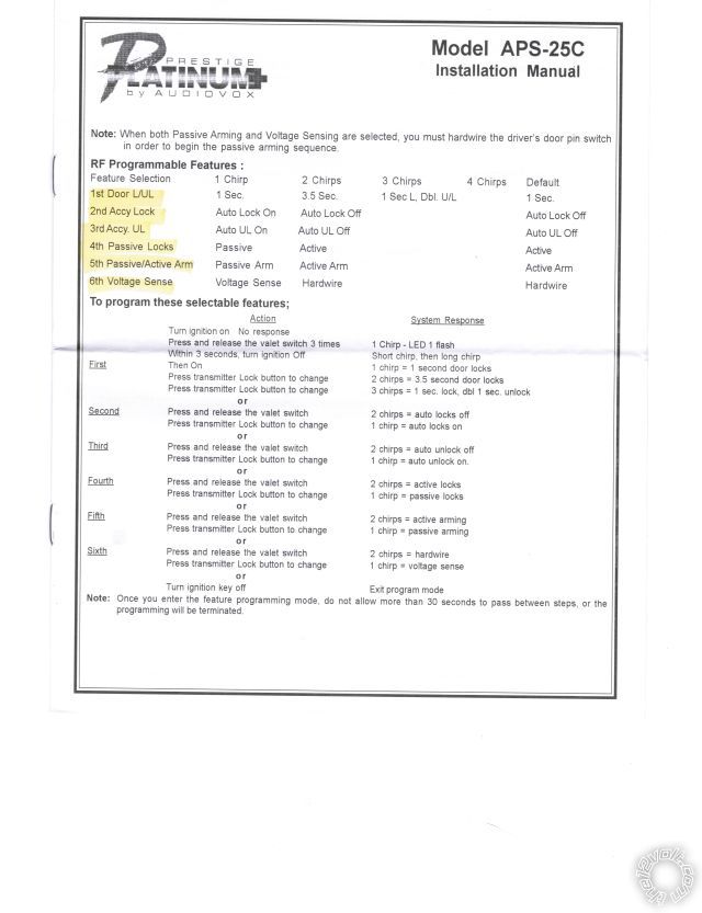
Installation complete now onto programming!! Lec do you have any experience getting into the programming mode on the Audiovox? I tried following the directions but they are confusing to me. Any advice?
Craig
prestige aps25c, 2011 nissan sentra - Page 2 -- posted image.
lectricguy 
Copper - Posts: 359
Copper spacespace
Joined: March 18, 2008
Location: Rhode Island, United States
Posted: January 09, 2011 at 3:04 PM / IP Logged  

Yes, I've done a ton of Audiovox.  

1.) Make sure the system is unlocked.

2.) turn the ignition key to the "on" position (past accessory, before start).

3.) press the programming button 3 times--you will hear 1 chirp from the horn.  You are now in bank 1, for adding or deleting transmitters. 

4.) You advance to the next bank (Bank 2--for Alarm feature programming) by turning the ignition to the "Off Position, then back to "On".   You will hear the horn honk as the ignition transitions to off, then a long honk as it transitions again to on.  You are now in bank 2.

5.) You now select which feature you want to change by pressing the valet button;   Each press the horn will honk indicating the settings--I.e., if the default is listed as 2 chirps, the horn will honk twice.  

6.)If you want to change that setting, press the Lock button on your transmitter--you will hear the honks for the next setting--in this example 3 honks.  If that is the desired setting, press the valet button to progress to the next feature; if you want to change to a different setting, press the lock button until the desired setting has benn selected.

7.) When you are done, you can turn the ignition off, and wait 15 seconds--the unit will exit programming mode.

Once you get the hang of it, the Avox programming is really fairly easy.  Let me know if you need more info.

Lectric Guy
craigmri 
Member - Posts: 17
Member spacespace
Joined: January 04, 2011
Location: Florida, United States
Posted: January 10, 2011 at 10:02 AM / IP Logged  
OK that makes much more sense Lec.....I just tried it again and believe I am in the correct mode now and as I would press the valet button it would give me a double honk for each feature until I reached what I think that the 6th feature(the one I want to change to voltage sense) and it sounds a long chirp and the lock button on the fib does nothing. I think the long chip indicates it ending programming? I'm missing a step somewhere.
Craig
lectricguy wrote:

Yes, I've done a ton of Audiovox.  

1.) Make sure the system is unlocked.

2.) turn the ignition key to the "on" position (past accessory, before start).

3.) press the programming button 3 times--you will hear 1 chirp from the horn.  You are now in bank 1, for adding or deleting transmitters. 

4.) You advance to the next bank (Bank 2--for Alarm feature programming) by turning the ignition to the "Off Position, then back to "On".   You will hear the horn honk as the ignition transitions to off, then a long honk as it transitions again to on.  You are now in bank 2.

5.) You now select which feature you want to change by pressing the valet button;   Each press the horn will honk indicating the settings--I.e., if the default is listed as 2 chirps, the horn will honk twice.  

6.)If you want to change that setting, press the Lock button on your transmitter--you will hear the honks for the next setting--in this example 3 honks.  If that is the desired setting, press the valet button to progress to the next feature; if you want to change to a different setting, press the lock button until the desired setting has benn selected.

7.) When you are done, you can turn the ignition off, and wait 15 seconds--the unit will exit programming mode.

Once you get the hang of it, the Avox programming is really fairly easy.  Let me know if you need more info.

lectricguy 
Copper - Posts: 359
Copper spacespace
Joined: March 18, 2008
Location: Rhode Island, United States
Posted: January 10, 2011 at 11:31 AM / IP Logged  

Craig-

There is a.requirement to go from bank 1 to bank 2 in (if iI recall correctly) 3 seconds.  Then once in bank2, there is a 15Second inactivity time--if there is no action, the system will exit program mode. 

So let's take this slow...

1.) Assuming the system is unlocked, turn the key to "on, press the valet button 3x.  You get 1 honk from the horn.

2.) Within 3 seconds, turn the ignition key to "off"  then immediately  to "On" again.  You will hear 2 honks, one at off, one at on.

3.) Now, assuming your APS25C is in default settings, press the valet (PBLED) once for Feature 1--Door L/UL--It should be default at 1Sec--You will hear 1 honk (Refer to your sheet above--1 sec setting under the  1 chirp column, default setting 1 sec).

--If you want to change this, press lock--2 chirps would be heard (3.5Sec setting), press lock again, 3 chirps are heard (1 sec lock,/doubl U/L), etc.   Once you have the appropriate setting selected, go to the next feature.

    The next feature (Feature 2, Accy Lock)) is accessed by pressing the valet (PBLED) again.  The default of  feature 2 is 2 chirps, Auto Lock Off, so you  

     should hear 2 chirps.  If this is the desired setting, Press the valet/PBLED again, to move to Feature 3, Accy UL.

    Feature 3 (accy UL) default is 2 chirps, auto lock off, so you should hear 2 chirps. 

You cycle through the features and settings this way until you are configured as desired.  If you wait longer than 15S between steps, the system will exit program mode--with a long chirp, and you need to reenable bank 2 programming mode to continue (i.e., start again at step 1 above).

Hope this helps.

Lectric Guy
Page of 3

  Printable version Printable version Post ReplyPost New Topic
You cannot post new topics in this forum
You cannot reply to topics in this forum
You cannot delete your posts in this forum
You cannot edit your posts in this forum
You cannot create polls in this forum
You cannot vote in polls in this forum

  •  
Search the12volt.com
Follow the12volt.com Follow the12volt.com on Facebook
Friday, April 26, 2024 • Copyright © 1999-2024 the12volt.com, All Rights Reserved Privacy Policy & Use of Cookies
Disclaimer: *All information on this site ( the12volt.com ) is provided "as is" without any warranty of any kind, either expressed or implied, including but not limited to fitness for a particular use. Any user assumes the entire risk as to the accuracy and use of this information. Please verify all wire colors and diagrams before applying any information.

Secured by Sectigo
the12volt.com spacer
Support the12volt.com
Top
the12volt.com spacer