the12volt.com spacer
icon

5902 remote start constant start mode


Post ReplyPost New Topic
< Prev Topic Next Topic >
kstundra 
Member - Posts: 15
Member spacespace
Joined: April 03, 2011
Location: Kansas, United States
Posted: April 03, 2011 at 3:09 PM / IP Logged  

I am installing a Viper 5902 (wiring very similar to 5701) This is going in a 2010 Tundra using a Key-Override-All because it has the 80 bit key. I've got everything hooked up, and was trying to teach the remote, but since it was acting flakey, I rechecked my wiring. Initially, I had a 3 mis-wires.

1) I had missed the BLACK/ white neutral safety input to ground.
2) I also had the Tach input miswired to the violet door trigger input (+), which I believe is not used on the Tundra.
3) And the dark blue (-) 200ma Status output, I had connected to the Key-Override-All, but not the gray wire keysense wire.
All of those have been corrected, but now it seems to always be in a remote starting mode. As soon as I connect the ground, it cranks and starts, but doesn't seem to keep running the starter, so it does sense that much. If I pull all of the fuses out of the heavy harness, it does not try to start, but does turn the headlights on. With those fuses out, but the harness still connected, if I insert the key and only turn to ON, it again starts. If I remove the heavy harness entirely, then it doesn't start.
To me, it seemed the problem might be in the ignition switch wiring, so I triple checked that. I'm pretty sure it's right, but to confirm:
If I pull the J9 plug out, cut the dark green wire , and connect the green Viper heavy harness wire to the plug side, that is also the key side? Then the other cut wire would go to Violet?
Then Red, and RED / Black go to constant +12. RED / White also goes to constant +12, or to a relay? the description field mentions Flex relay input 87.

Also, when the engine is running, neither the brake nor the hood pin grounded (hood up) stop the engine, which I thought they should.

I would really appreciate any ideas, as it's difficult to troubleshoot this when it's constantly trying to start.
Thanks

t&t tech 
Platinum - Posts: 2,608
Platinum spacespace
Joined: October 05, 2008
Location: Trinidad and Tobago
Posted: April 03, 2011 at 5:35 PM / IP Logged  

Do you have the WHITE/ blue wire on the h1 harness connected to anything?

commit your way to jehovah and he will act in your behalf. psalms 37:5
howie ll 
Pot Metal - Posts: 16,466
Pot Metal spacespace
Joined: January 09, 2007
Location: United Kingdom
Posted: April 03, 2011 at 5:49 PM / IP Logged  
Double check the rest of your wiring, then remove all fuses, reconnect the ground, then replace the fuses.
kstundra 
Member - Posts: 15
Member spacespace
Joined: April 03, 2011
Location: Kansas, United States
Posted: April 03, 2011 at 5:50 PM / IP Logged  
No, WHITE/ blue is not connected to anything.
syl20rochon 
Copper - Posts: 298
Copper spacespace
Joined: October 16, 2009
Location: Ontario, Canada
Posted: April 03, 2011 at 7:16 PM / IP Logged  
check the ignition switch wiring...
5902 remote start constant start mode -- posted image.
Please correct wiring and then disconnect your bypass...put your key into the ignition switch and try to start the trunk with the remote...se what happens...
*Make sure you learn your tach.
*Make sure your remote starter is in automatic mode and not manual mode.
*Yes, your small BLACK/ white needs to be at ground.
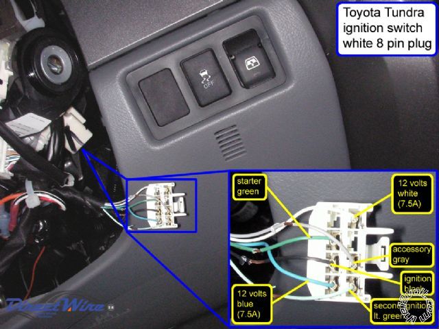
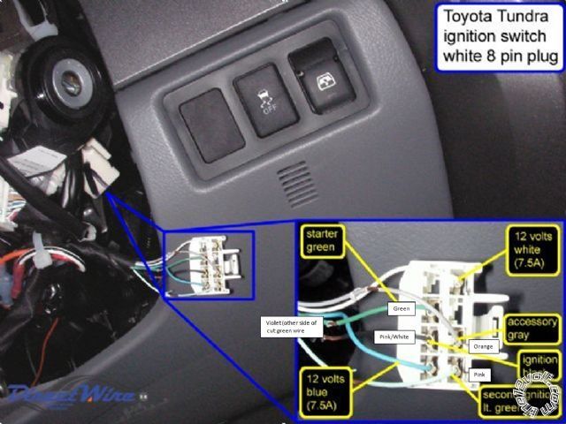
*Make sure your large pink/white wire is configured to second ignition and not second accessory.
*the large green wire shouldn't be used unless you're using the starter kill onboard relay.
*All three red wires need to be connected to +12V. (Red,RED / white,RED / black)
*Make sure your ground is good and not loose.
Sylvain Rochon
MECP security specialist
Tech support for remote starters
26 Years of experience counts
I'm here to help.
kstundra 
Member - Posts: 15
Member spacespace
Joined: April 03, 2011
Location: Kansas, United States
Posted: April 03, 2011 at 8:22 PM / IP Logged  

Thanks for the reply Sylvain. Your picture does not match what I have wired. Here is what I have. I'm not sure if I have the starter kill onboard relay (is that the case where you cut the ignition green wire?). Something I can add is even with the neutral safety switch off or even removed, it still starts. I would think that switch would kill the engine in every case. Also, what is the difference between ignition1 and ignition 2?

Is there such thing as a hard reset on this alarm? Like return everything to factory defaults. I know that's not my problem, but I'm not real sure what state the  brain, or key fobs are.

Thanks again.

5902 remote start constant start mode -- posted image.

syl20rochon 
Copper - Posts: 298
Copper spacespace
Joined: October 16, 2009
Location: Ontario, Canada
Posted: April 03, 2011 at 8:40 PM / IP Logged  
First, you never cut the ignition wire because if the relay fails, you truck will stop.
Ignition 1=Pink from R/S to black from truck
Ignition 2=Pink/white from R/S to light green from truck
Starter=Purple from R/S to Green from truck
Accessory=Orange from R/S to gray from truck
The Green wire you don't use and you'll have no wires to cut in 2.
Red..RED / white..RED / black from R/S to blue +12V from truck
Little brown wire to cold side of Brake pedal. (12v when pedal is pushed)
White wire to parking light wire...watch for polarity and install fuse in proper position
Little gray wire to hood switch if installed (Don't need to)
Little PURPLE / white to tach wire
Littel BLACK/ white to ground.
Sylvain Rochon
MECP security specialist
Tech support for remote starters
26 Years of experience counts
I'm here to help.
howie ll 
Pot Metal - Posts: 16,466
Pot Metal spacespace
Joined: January 09, 2007
Location: United Kingdom
Posted: April 03, 2011 at 8:51 PM / IP Logged  
First poster, don't worry you didn't cut the ignition, how it,s supposed to be wired is that the starter wire is cut, thick green goes to key side and thick violet to starter side.
This acts as a starter cut when the alarm is on and an anti-grind when the R/s is activated.
Ignition 1 is the primary ignition it stays live during cranking.
Ignition 2 along with the accessory dumps on the cranking cycle.
ACC and ign 2 are used to power circuits not necessary to actually start the vehicle such as window lifts, wipers HVAC. All vehicles will dump these circuits during the starting cycle.
Please try what I originally suggested.
kstundra 
Member - Posts: 15
Member spacespace
Joined: April 03, 2011
Location: Kansas, United States
Posted: April 03, 2011 at 9:32 PM / IP Logged  
So, Sylvain and Howie, you guys do not agree on which way the ignition is to be wired? Howie, are you saying what I have is correct, specifically, heavy green wire goes to plug side of cut green ignition wire? What's the significance of reattaching the ground, then replacing all fuses? Is there any particular order to the fuse replacement?
syl20rochon 
Copper - Posts: 298
Copper spacespace
Joined: October 16, 2009
Location: Ontario, Canada
Posted: April 03, 2011 at 10:14 PM / IP Logged  
What I'm saying is that starter kill connection is not needed to have the system function properly. If you wish to make the connection, do it...green wire on connector's side and purple wire on the starter's side (opposite side of the ignition connector). It's a matter of choice. If you have connected all the wire like I mentioned above and you still have the starter kicking in every time you connect the ground, you might have a defective module. If properly connected, you shouldn't have anything cranking by itself. Also, did you tape all your ignition wires together? You might have pointy wires piercing the 12v constant wire making your starter crank. One thing that I would do is that I would disconnect the purple wire from the ignition switch, take my multimeter out and measure if constant voltage is coming out of the module when ground is connected.
Sylvain Rochon
MECP security specialist
Tech support for remote starters
26 Years of experience counts
I'm here to help.
Page of 3

  Printable version Printable version Post ReplyPost New Topic
You cannot post new topics in this forum
You cannot reply to topics in this forum
You cannot delete your posts in this forum
You cannot edit your posts in this forum
You cannot create polls in this forum
You cannot vote in polls in this forum

  •  
Search the12volt.com
Follow the12volt.com Follow the12volt.com on Facebook
Monday, April 29, 2024 • Copyright © 1999-2024 the12volt.com, All Rights Reserved Privacy Policy & Use of Cookies
Disclaimer: *All information on this site ( the12volt.com ) is provided "as is" without any warranty of any kind, either expressed or implied, including but not limited to fitness for a particular use. Any user assumes the entire risk as to the accuracy and use of this information. Please verify all wire colors and diagrams before applying any information.

Secured by Sectigo
the12volt.com spacer
Support the12volt.com
Top
the12volt.com spacer