the12volt.com spacer
icon

two stage unlock ca 6551


Post ReplyPost New Topic
< Prev Topic Next Topic >
elocin671 
Member - Posts: 10
Member spacespace
Joined: April 15, 2011
Location: Washington, United States
Posted: April 15, 2011 at 11:28 AM / IP Logged  

Hi, I was wondering if anyone could help me wire up the 2-stage/priority unlock feature?

I have a Code Alarm 6551 module. In the manual it says I can activate the feature. But I dont see an output for it. Im pretty sure I need to use a relay.

Im trying to get it installed in a 2000 Isuzu Rodeo. Here are links to the manual and Isuzu diagram. I appreciate any help. Thanks in advance.

http://a248.e.akamai.net/pix.crutchfield.com/Manuals/220/220CA6551.PDF

https://www.the12volt.com/installbay/alarmdetail/1174.html

howie ll 
Pot Metal - Posts: 16,466
Pot Metal spacespace
Joined: January 09, 2007
Location: United Kingdom
Posted: April 15, 2011 at 1:04 PM / IP Logged  
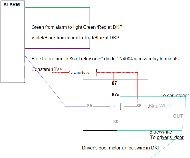
I've done a diagram in Word for you, but I can't convert it to an acceptable file!
Don't know how!
PM me with your email address and I'll email it to you.
Essentially you will need a standard Bosch type cube relay and a 1N4004 diode, both available from either Radio Shack or Crutchfield.
Press lock/arm and all doors will lock, press unlock/disarm and the driver's door only will unlock.
Press aux 1 and the other doors will unlock.
DKP on the diagram is the driver's kick panel.
elocin671 
Member - Posts: 10
Member spacespace
Joined: April 15, 2011
Location: Washington, United States
Posted: April 15, 2011 at 8:25 PM / IP Logged  

Thanks for the diagram! I was wondering if I could use the trunk release output, instead of aux 1 for the rest of the doors to unlock?

This is so that I press the unlock button once, it unlocks drivers door. hold unlock for 3 seconds, this activates trunk output to unlock all doors.

And then Aux 1 will be open, and I can use it for illuminated entry. Does that sound ok? I dont have a trunk release anyway.

Heres the diagram you made. If you use word to make these diagrams, just press "print screen" on your keyboard.

Then open up MS Paint or other image creation program. Press "Ctrl-P" to "paste" the screen shot into the paint program, then adjust as you see fit.

two stage unlock ca 6551 -- posted image.

elocin671 
Member - Posts: 10
Member spacespace
Joined: April 15, 2011
Location: Washington, United States
Posted: April 15, 2011 at 8:28 PM / IP Logged  
*^^oops, I meant "Ctrl+V" to paste. Then save it as a image file, .jpg, .bmp, .png, etc... 
howie ll 
Pot Metal - Posts: 16,466
Pot Metal spacespace
Joined: January 09, 2007
Location: United Kingdom
Posted: April 16, 2011 at 2:51 AM / IP Logged  
Of course you can use the trunk release, I couldn't find it last night when I skimmed the attachments...sorry. It would have been my first choice also. I couldn't find the relay in R/Shack, but most auto parts stores sell them; the type you're after is an SPCO.
The diode with it's band (cathode) towards 86 is there to protect the alarm's circuitry against back feed from the relay, for your convenience it's MANDATORY!
Many, many thanks for the advice.
lectricguy 
Copper - Posts: 359
Copper spacespace
Joined: March 18, 2008
Location: Rhode Island, United States
Posted: April 16, 2011 at 6:32 AM / IP Logged  

elocin671-

Please be aware that for 2nd press unlock, the 6551 does not use the AUX output, but rather uses one of the two available Factory Disarm outputs.  This is the Lt. GREEN/ Black wire in the 6 pin output harness.  This output is programmable in Feature Bank 3, and would allow you to press unlock once for driver's door, press unlock a second time for all doors. This would allow you to keep the trunk release output (holding the unluck for 3 seconds) as well.  There is another Factory disarm output in the 4 pin auxillary harness that operates exactly the same for factory disarm and is uneffected by this programming.

From the Install manual:

< size=1 face=Arial>< size=1 face=Arial>

2 - Factory Disarm: < size=1 face=Arial>< size=1 face=Arial>Controls the timing of the LT. GREEN/ BLACK factory disarm

wire on the 6 pin output harness only and does not change the output of the factory

disarm wire on the 4 pin alternate output harness.

Factory Disarm - Single 1 second pulse with unlock and remote start

activation.

2nd Unlock - Same ouput as unlock with 2nd press of unlock only.

Start Status - Continuous ( - ) output during the remote start cycle.

Lectric Guy
elocin671 
Member - Posts: 10
Member spacespace
Joined: April 15, 2011
Location: Washington, United States
Posted: April 16, 2011 at 10:58 AM / IP Logged  

howie ll wrote:
Of course you can use the trunk release, I couldn't find it last night when I skimmed the attachments...sorry. It would have been my first choice also. I couldn't find the relay in R/Shack, but most auto parts stores sell them; the type you're after is an SPCO.
The diode with it's band (cathode) towards 86 is there to protect the alarm's circuitry against back feed from the relay, for your convenience it's MANDATORY!
Many, many thanks for the advice.

I just came from the local Radio shack and 3 big box auto part stores with no luck. I'll try some other car audio/electronics stores.

I did pick up a 4-pin relay and socket, im hoping to use it for anti-grind/starter kill. Thanks for all the help!

lectricguy, thanks for that info. Im actually tearing in to it right now, while I have the chance. Darn Seattle weather and having no garage. Lol.

So if I understand correctly. I wire the alarms unlock wire to just the drivers door, using relay since its a positive trigger.

Then I have 2 factory disarm/pulse before start lines. The main 6-pin one will be wired to the rest of the doors.

The alternate 4-pin one, will go to my vehicles factory disarm wire. The alternate factory disarm wire does not get affected by programming 2-stage unlock in bank 3.

I was under the impression that the factory disarm/pulse before start. Would send an unlock pulse to the doors right before remote start, and I wouldnt want that.

But if I program it in bank 3, it will not unlock the doors before remote start? If so, then I will go that route.

I just found it odd, that there is a feature for the two-stage unlock. But no specific output on the module itself, so its a little confusing.

If anything, I dont ming losing my trunk output. Like I mentioned earlier, I dont have a trunk release.

So can you just confirm if I am understanding correctly? Im getting eveything prepped right now. Thanks again!

howie ll 
Pot Metal - Posts: 16,466
Pot Metal spacespace
Joined: January 09, 2007
Location: United Kingdom
Posted: April 16, 2011 at 11:12 AM / IP Logged  
Right, the relay you have, four terminals is technically a SPNO, i.e. one pole not connected.
The type we are after is a SPCO, i.e. Single pole changeover.
At rest 30 and 87a are connected. Once the coil 85 and 86 are activated, 30 disconnects from 87a and connects to 87, thus the changeover.
In electronic terms:
30 = common
87 = NO (normally open)
87a = NC (normally closed)
Since normally (see my diagram) the blue/white driver's door lock motor is joined we have to retain that configuration, thus we need a 5 terminal relay. If you use a 4 terminal, without going into detail, you will at the least blow the fuse controlling your power locks. Look at the excellent relay section on this site.
By the way your locks are NEG. pulse, not POS. as you stated in your last post.
elocin671 
Member - Posts: 10
Member spacespace
Joined: April 15, 2011
Location: Washington, United States
Posted: April 16, 2011 at 11:27 AM / IP Logged  

howie ll, thanks for the tip. I read up in the relay section, good stuff. I have a SPCO relay that came with the Code alarm, so im going to use that.

lectricguy, I just read the manual again. So if I program bank 3, the second unlock will activate the unlock output on the module.

So I connect the alternate factory disarm to my vehicles factory disarm line. This line does not change with programming of bank 3.

Connect the alarms unlock output to the rest of my vehicles unlock wire. This will unlock on 2nd press on remote.

Then I am just confused on where to connect the drivers unlock wire. I think its should to go to the 6-pin factory disarm.

So press the remote once and it unlocks the drivers door. I just dont want it to unlock before remote start.

Im I getting closer? Lol. Sorry for being a noob, this is my first alarm install. I have only done some basic audio set-ups.

lectricguy 
Copper - Posts: 359
Copper spacespace
Joined: March 18, 2008
Location: Rhode Island, United States
Posted: April 16, 2011 at 11:40 AM / IP Logged  

To clarify, the lt GREEN/ black wire is multi purpose.  If left in the factory default mode, it functions as factory disarm pulse.  If programmed (in feature bank 3, 2nd item) to operate as 2nd unlock, the wire pulses the second time unlock is depressed.   No relationship to factory disarm.  For the record, the output may be programmed for Status output (outputs ground while remote start is running).  All of these settings are mutually exclusive; programmed for 2nd unlock, that is all the output does. 

None of this programming effects the 4pin Alternate harness, the operation of that factory disarm output remains the same, regardless of   feature bank 3, 2nd item programming.

Your comment:

So if I understand correctly. I wire the alarms unlock wire to just the drivers door, using relay since its a positive trigger.

Then I have 2 factory disarm/pulse before start lines. The main 6-pin one will be wired to the rest of the doors.

The alternate 4-pin one, will go to my vehicles factory disarm wire. The alternate factory disarm wire does not get affected by programming 2-stage unlock in bank 3.

 Correct.

Lectric Guy
Page of 2

  Printable version Printable version Post ReplyPost New Topic
You cannot post new topics in this forum
You cannot reply to topics in this forum
You cannot delete your posts in this forum
You cannot edit your posts in this forum
You cannot create polls in this forum
You cannot vote in polls in this forum

  •  
Search the12volt.com
Follow the12volt.com Follow the12volt.com on Facebook
Wednesday, May 8, 2024 • Copyright © 1999-2024 the12volt.com, All Rights Reserved Privacy Policy & Use of Cookies
Disclaimer: *All information on this site ( the12volt.com ) is provided "as is" without any warranty of any kind, either expressed or implied, including but not limited to fitness for a particular use. Any user assumes the entire risk as to the accuracy and use of this information. Please verify all wire colors and diagrams before applying any information.

Secured by Sectigo
the12volt.com spacer
Support the12volt.com
Top
the12volt.com spacer