the12volt.com spacer
icon

inline fuse and measuring vpwr wire amps?


Post ReplyPost New Topic
< Prev Topic Next Topic >
howie ll 
Pot Metal - Posts: 16,466
Pot Metal spacespace
Joined: January 09, 2007
Location: United Kingdom
Posted: April 28, 2011 at 3:37 AM / IP Logged  
Your on to the right idea interrupting either of the coil feeds, except they are both probably in bus bars in the fusebox. Is there a fuse marked Engine Control anywhere? That's the one to go for, except in practical terms cutting any ignition/run (as against starter) is DANGEROUS.
oldspark 
Gold - Posts: 4,913
Gold spacespace
Joined: November 03, 2008
Location: Australia
Posted: April 28, 2011 at 5:59 AM / IP Logged  
madmanuser - thanks for asking for more. Being new to this is no problem, but I have troubles assessing poster's knowledge, and others get cheesed off else run off the road after falling asleep with my long replies...
Forget cutting - at least in terms of power etc.
Placing a switch in a solid link is an extra point of failure. Wire falls off, connectors or switch corrode or fail... Bingo - no go!
Guaranteed that happens as on a level crossing in front of that freight train, or driving the loved one to hospital... in fact - anywhere!
Even if a mere relay-ground switch (#85 to ground), compare - with simple consideration only - a #85 connector to wire to ground connector to ground to a #85 connector to wire to switch connector thru switch contacts out switch connector to wire to ground connector to ground.
Which has the greater risk of failure, and by how much?
My suggestion to switch (interrupt) a relay-coil's ground was merely in preference to interrupting the relay's much higher power output or source. (Removing its fuse is ok though, but that could wear the fuse contacts...)
Besides, isn't stopping a relay from energising the same as interrupting its power? Carry a spare (or the original) #85 to ground cable and easily restore a failed switch circuit.
(Yeah, ok, smart stealer merely jumpers the #30 - #87 contacts, but they have to know what is wrong AND which relay - and it won't be clicking to assist them!)
But to disable ignition...
Typical ignitions involve grounding a hot ignition coil and breaking that ground for the spark. (+12V from IGN +12V to coil+. The coil- is grounded to charge the coil, then broken/opened to get the spark across its secondary winding.)
Maybe see http://en.wikipedia.org/wiki/Ignition_system but... why is it I can never find the diagrams I am looking for???!!!... I think these diagrams are better...
From
www.oldmarineengine.com/discus/messages/2/95648.html but resized:
inline fuse and measuring vpwr wire amps? - Page 2 -- posted image.
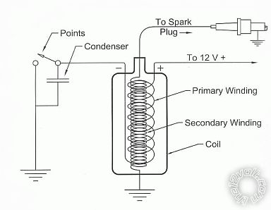
....which shows the grounded IgCoil and its +12V supply, and the points/contacts that open and close to ground.
And from www.allaboutcircuits.com/worksheets/specialq.html:
inline fuse and measuring vpwr wire amps? - Page 2 -- posted image.
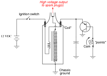
... is the equivalent but shows how the +12V coil supply is IGN switched, and the points are buffered by a transistor.
That transistor could be ant transistorised ignition - eh, HEI etc (but not CDI = Capacitive Discharge Ignition!).
In BOTH cases, the coil- is interrupted to produce spark.
If it is NOT interrupted, then no spark.
So if the points or transistor is short-circuited to ground, no spark.   
How? Simple! A hard wire from coil- to ground. Short or fat enough to handle coil current (typically 5-10A).
Add a switch to break or open that short, and the system functions normally.
That is merely an addition to existing wiring, and can be easier to hide. There is no cutting of wires.
And if the wire to the switch shorts, or the switch fails, just cut or disconnect that wire.
The catch? The coil has continual current through it. Eventually it may overheat and be damaged or fail.
But old coils usually had enough thermal inertia to be okay for 10 minutes or more.
Newer coils (E-types etc) might have reasonable thermal inertia.
(Author's note to self: Suggest to readers to carry a spare coil - just in case...?)
FYI - electronic ignitions usually have a means of cutting power after a certain time to prevent coils melting.
But that's only a problem if the thief leaves the IGN +12V on...
But the if the coil melts, they can't drive the vehicle can they?
(Where did I put that reminder note?)
BUT if it's a CDI system, that's totally different. You can probably short the pickup (points; else reluctor, optical or Hall-effect sensors) but not the coil-.
In a CDI, the CDI switches high-voltage DC to the coil (typically 300V - 450V) and shorting that can damage the CDI capacitors or circuit. (CDIs use the IgCoil as an "impulse" transformer; the coil does not charge as with points and transistorised ignitions. Hence CDIs can be used to 30,000 RPM etc!)
That shorting principle (to ground) can apply to many vehicle sensors. That's because many are "open collector" outputs. That's just like points - either they are grounded, else they are open and floating. It's a common signaling arrangement for various reasons - in particular between systems at different supply voltages. Computer chips use it inside PCs.
But that for on-off sensors only - like grounding oil pressure switches, handbrakes, most door switches etc.
Find the right sensor(s) which - if disabled - prevent the vehicle form starting or running, and they may be other or additional options. Diode-OR those sensors to a single grounding switch to   disable all those inputs. (Poor thief - jumper new ignitor or points/pickup wires - still no go. Jumper the airflap - still no go. Hey - there's another car....
Sorry for the Ignitions-101 ramble.
Luckily Stargate Universe is on the TV so I'll save you from more....
howie ll 
Pot Metal - Posts: 16,466
Pot Metal spacespace
Joined: January 09, 2007
Location: United Kingdom
Posted: April 28, 2011 at 6:07 AM / IP Logged  
And they've shut down Stargate Universe halfway through the current season load of #@".
Will this car have a separate coil?
I've not really done any coil - (31) grounding since the early 70s.
You might also simply ground the sensor side of the camshaft position sensor, if the vehicle has an engine management system. i.e. 12V+ ignition, ground and trigger; ground the trigger.
madmanuser 
Member - Posts: 39
Member spacespace
Joined: April 26, 2011
Posted: April 28, 2011 at 2:48 PM / IP Logged  
Howie - when you say it is dangerous to cut ignition, is this because of the possibility of accidentally cutting it while driving and the possibility of losing power while on the road? Or a connection failing and then cutting power while on the road?
Also, sorry, but I'm not sure what you mean by separate coil. The car has only one ignition coil at the moment. It is stock ignition.
This is what the coil looks like, but it's a stock one not msd
http://www.americanmuscle.com/msd-tficoil-8695.html
Oldspark - WOW! good info haha. definitely learned something new. I don't know how I could hard wire my coil, it has a stock plastic connector that the wires are in and that connector snaps onto the coil I am not sure what kind of ignition i have <---nooob! I know I have a tfi coil and a tfi module on the distributor.
I found this schematic for a similar year mustang. it is correct for my car so I have been using it. take a look
http://brembs.net/cars/maf_conversion/mustang_wiring.jpg
Either way I found this remote controlled relay and I wanted to use it to control the EEC power relay. Also I have my dash out so I can hide the relay somewhere good!
I don't know how comfortable I am locating sensors and shorting them.
Hey! do you think I could short the power wire to the coil for the EEC power relay? If I understood you correctly the current or power would go towards the ground and the relay would not receive any power. Or would it just make sense to use a relay to control the power for the coil to the EEC power relay?
Thanks again. I feel I am getting closer to figuring this out and another step closer to taking my baby out on the road!
howie ll 
Pot Metal - Posts: 16,466
Pot Metal spacespace
Joined: January 09, 2007
Location: United Kingdom
Posted: April 28, 2011 at 3:58 PM / IP Logged  
yes
howie ll 
Pot Metal - Posts: 16,466
Pot Metal spacespace
Joined: January 09, 2007
Location: United Kingdom
Posted: April 28, 2011 at 4:01 PM / IP Logged  
Two wires on that coil. When you disconnect that plug and turn on the ignition, one reads 12 volts+, the other nothing. If you ground the "nothing" wire with a secret switch, (safer than the R/Controlled relay), the car simply won't start.
But to be honest, someone like me would find it in 2 seconds.
madmanuser 
Member - Posts: 39
Member spacespace
Joined: April 26, 2011
Posted: April 28, 2011 at 4:22 PM / IP Logged  
Howie - so if I'm willing to take the risk of the car shutting down on the road by wiring a relay to the EEC power relay wouldn't this be more difficult for someone to find as compared to grounding the ignition like you mentioned above?
The EEC power relay is tucked deep in the kick panel and by disabling the eec power relay wouldn't it be hard for a thief to figure out why nothing is getting power when they turn attempt to turn the vehicle on? Also without ripping the dash out again I doubt anyone would ever find the relay. I see the entire wiring harness and I can find a way to make sure that the wires and relay are hiding extremely deep behind the dash
howie ll 
Pot Metal - Posts: 16,466
Pot Metal spacespace
Joined: January 09, 2007
Location: United Kingdom
Posted: April 28, 2011 at 4:37 PM / IP Logged  
We are running around in circles. If you must immobilise it's safer to ground rather than cut. Second, the first thing I look for with a "mystery" breakdown apart from the obvious fuel supply is engine bay power.
A single grounding wire if properly loomed in will be MUCH harder to find.
Third from your questions and lack of theoretical knowledge, don't do this.
oldspark 
Gold - Posts: 4,913
Gold spacespace
Joined: November 03, 2008
Location: Australia
Posted: April 28, 2011 at 5:03 PM / IP Logged  
x2. Think about it - vibration, heat, faifique, installation and meterial quality.... Your car stops anywhere anytime anyspeed anyrain anybend anyrailwaycrossing any freeway entrance etc etc etc.
Usually "cut" or "active supply" systems are set up with redundancy - ie, two switches, two relays, 2 parallel sets if wiring. But that is useless unless monitoring is available to alert the failure of one of the supplies (useless - other than perhaps maybe halving the chance of failure).
Hence the short/bypass system is used in preference....
But yes - circles x2 too.
PS - I did points-shorts in the 00s (that's 2000s - not 1900s!) but that was on ignitor circuits and some transistorised (HEI) which is the same thing - a connection else not to ground to the coil-.
madmanuser 
Member - Posts: 39
Member spacespace
Joined: April 26, 2011
Posted: April 29, 2011 at 10:12 PM / IP Logged  
Ok sorry for the circles. I re-read the entire thread and have a better understanding of what you recommend. I see why you recommend it and have decided even though I don't have as great a knowledge of electrical circuits that I will continue. Hopefully you guys can help me do this right. Again I want to thank you for your patience and help.
Two quick (maybe not so quick :-D) question sorry!
Now I have checked the coil and located the wire which does NOT receive +12v when the ignition is on.(I will call this wire "ign coil ground wire")
I don't want the thief to find my grounding wire. Does it matter where on this ignition coil ground wire I wire in my switch? Does it have to be very close to the coil?
I noticed that the wire goes to my EEC and my tfi module as well. My research on my vehicles ignition system indicates that the tfi module is the device which switches ground for the coil allowing spark to be sent to the distributor. It may make a huge difference where I wire in my switch.
Old spark you said my switch should be "hardwired" into the ign coil ground wire. Does this mean it has to be attached at the connector that connects to my ign coil? Or can I tap into the ign coil ground wire and splice/solder in my wire at any point on the ign coil ground wire?
My preference would be to tap into the ign coil ground wire near my EEC inside the car.
My other question is if someone happens to know I have grounded/shorted out my ign wire, would they have to find the switch wired into it to start the car or can they just wire my ign coil straight to my tfi module?
Thanks again
Page of 3

  Printable version Printable version Post ReplyPost New Topic
You cannot post new topics in this forum
You cannot reply to topics in this forum
You cannot delete your posts in this forum
You cannot edit your posts in this forum
You cannot create polls in this forum
You cannot vote in polls in this forum

  •  
Search the12volt.com
Follow the12volt.com Follow the12volt.com on Facebook
Saturday, May 18, 2024 • Copyright © 1999-2024 the12volt.com, All Rights Reserved Privacy Policy & Use of Cookies
Disclaimer: *All information on this site ( the12volt.com ) is provided "as is" without any warranty of any kind, either expressed or implied, including but not limited to fitness for a particular use. Any user assumes the entire risk as to the accuracy and use of this information. Please verify all wire colors and diagrams before applying any information.

Secured by Sectigo
the12volt.com spacer
Support the12volt.com
Top
the12volt.com spacer