the12volt.com spacer
icon

diode confusion


Post ReplyPost New Topic
< Prev Topic Next Topic >
powerking 
Member - Posts: 20
Member spacespace
Joined: April 18, 2011
Location: Connecticut, United States
Posted: April 26, 2011 at 6:52 PM / IP Logged  

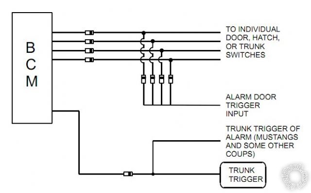
Why am I having such a brain lapse when it comes to diodes?? I have my 2001 F150 supercrew that I finally found the Doemlight supervison of BLACK/ lt blue, on the pass kick panel. This seems to be the easiest route for door triggers as, the domelight always comes on whenever any of the 4 doors gets opened. my questions is, how do I install the diode in this circuit? I am drawing a complete blank, does anyone have a diagram as to how it woudl actually "look"?

Thanks

Richdiode confusion -- posted image.

syl20rochon 
Copper - Posts: 298
Copper spacespace
Joined: October 16, 2009
Location: Ontario, Canada
Posted: April 26, 2011 at 6:59 PM / IP Logged  
There you go...hope that it helps
diode confusion -- posted image.
Sylvain Rochon
MECP security specialist
Tech support for remote starters
26 Years of experience counts
I'm here to help.
powerking 
Member - Posts: 20
Member spacespace
Joined: April 18, 2011
Location: Connecticut, United States
Posted: April 26, 2011 at 7:12 PM / IP Logged  

..thank you, but thats just the thing...Does my Truck have a BCM?  I havent even found my GEM yet!! It is supposed to be to the right of the gas pedal..The only thing I see is the SRS module.....Defintely not going there!!! all I'm really trying to do is hook up the door triggers to the CA 6551. I cant locate any of the said door triggers, and thats why I'm looking into the domelight wire to use for the door trigger.

Thanks guys

Rich

syl20rochon 
Copper - Posts: 298
Copper spacespace
Joined: October 16, 2009
Location: Ontario, Canada
Posted: April 26, 2011 at 7:18 PM / IP Logged  
Follow this
"The BLACK / YELLOW catches the drivers door and the BLACK/ pink catches the passengers door. The wires are found in their respective door harnesses. On the Super Crew the rear door trigger is BLACK/ lt. blue low in the driver kick panel. Use all wires and diode isolate each. See DirectFax document 1076 for wiring information. Both wires may also be found at the GEM module located above the fuse box. On models without a dome light delay use ORANGE / lt. green (-) at the light switch."
Follow the diagram above because you need to isolate the doors switches to make it work properly
Sylvain Rochon
MECP security specialist
Tech support for remote starters
26 Years of experience counts
I'm here to help.
powerking 
Member - Posts: 20
Member spacespace
Joined: April 18, 2011
Location: Connecticut, United States
Posted: April 26, 2011 at 7:46 PM / IP Logged  

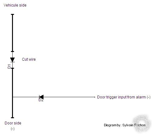
So for example, the dr door...blk / YELLOW, all I would do Is tap into that with the alarm trigger wire and insert the diode inline? Which way do I place the stripe end of the diode?

Thanks!

Whew..it has been a LONG time since I insalled alarm in my 1985 Renault!!

Rich

syl20rochon 
Copper - Posts: 298
Copper spacespace
Joined: October 16, 2009
Location: Ontario, Canada
Posted: April 26, 2011 at 7:56 PM / IP Logged  
Do this and repeat for the other doors....
diode confusion -- posted image.
Sylvain Rochon
MECP security specialist
Tech support for remote starters
26 Years of experience counts
I'm here to help.
i am an idiot 
Platinum - Posts: 13,667
Platinum spaceThis member consistently provides reliable informationspace
Joined: September 21, 2006
Location: Louisiana, United States
Posted: April 26, 2011 at 8:02 PM / IP Logged  

diode confusion -- posted image.

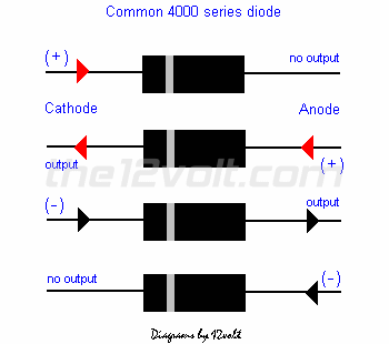
I did not read the above, but this diagram helps me when I have a brain lapse.

powerking 
Member - Posts: 20
Member spacespace
Joined: April 18, 2011
Location: Connecticut, United States
Posted: April 26, 2011 at 8:06 PM / IP Logged  

You guys really ROCK! I truly do appreciate the info that is given in this forum!

Thanks

Richdiode confusion -- posted image.

syl20rochon 
Copper - Posts: 298
Copper spacespace
Joined: October 16, 2009
Location: Ontario, Canada
Posted: April 26, 2011 at 8:11 PM / IP Logged  
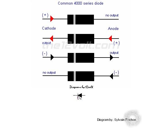
Diode explained.
diode confusion -- posted image.
Sylvain Rochon
MECP security specialist
Tech support for remote starters
26 Years of experience counts
I'm here to help.
powerking 
Member - Posts: 20
Member spacespace
Joined: April 18, 2011
Location: Connecticut, United States
Posted: April 26, 2011 at 8:14 PM / IP Logged  
Last thing...the band on the diode faces the door side correct?
Page of 2

  Printable version Printable version Post ReplyPost New Topic
You cannot post new topics in this forum
You cannot reply to topics in this forum
You cannot delete your posts in this forum
You cannot edit your posts in this forum
You cannot create polls in this forum
You cannot vote in polls in this forum

  •  
Search the12volt.com
Follow the12volt.com Follow the12volt.com on Facebook
Saturday, April 20, 2024 • Copyright © 1999-2024 the12volt.com, All Rights Reserved Privacy Policy & Use of Cookies
Disclaimer: *All information on this site ( the12volt.com ) is provided "as is" without any warranty of any kind, either expressed or implied, including but not limited to fitness for a particular use. Any user assumes the entire risk as to the accuracy and use of this information. Please verify all wire colors and diagrams before applying any information.

Secured by Sectigo
the12volt.com spacer
Support the12volt.com
Top
the12volt.com spacer