the12volt.com spacer
icon

safe to wire pin 30 to pin 86?


Post ReplyPost New Topic
< Prev Topic Next Topic >
madmanuser 
Member - Posts: 39
Member spacespace
Joined: April 26, 2011
Posted: May 17, 2011 at 11:47 PM / IP Logged  
i am an idiot wrote:

It does not matter where it gets put on the wire.  It can be before 30.  I always solder the diode to the base of 85 and 86.  Place the relay on the edge of a table or bench, set the diode on the relay and bend the legs to the appropriate length, solder the legs to 85 and 86, this leaves plenty room to install the connectors to the terminals of the relay.  It makes a neat install and it is more maintenence free than soldering the diode to a wire that is subject to moving.

I hear ya, but i am using relay sockets which eliminate the chance of me doing this. safe to wire pin 30 to pin 86? - Page 2 -- posted image.
oldspark 
Gold - Posts: 4,913
Gold spacespace
Joined: November 03, 2008
Location: Australia
Posted: May 18, 2011 at 4:30 AM / IP Logged  
Yeah - effectively Idiot means the same - wire direct between the socket pins...
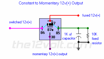
It's a pity an early post Diodes across relay coil doesn't include a simple pic like...
safe to wire pin 30 to pin 86? - Page 2 -- posted image.
.. but without the RHS resistor and cap.
The diode as shown is the same as a quenching diode.
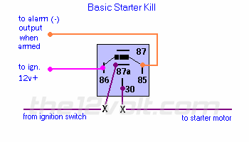
Maybe the next is better?
safe to wire pin 30 to pin 86? - Page 2 -- posted image.
awdeclipse 
Copper - Posts: 285
Copper spacespace
Joined: August 05, 2007
Location: Michigan, United States
Posted: May 18, 2011 at 7:59 AM / IP Logged  
The last relay socket I used, you can easily remove the pins from the socket. This should give you access to the bare pin which you can then solder directly to. It is not as "stable" as soldering directly to the relay legs but as a bonus you will have a permanent diode installed for that particular socket.
At least with this method you will have the advantage of the socket holding the pins fairly snug as opposed to attaching the diode to wires only.
howie ll 
Pot Metal - Posts: 16,466
Pot Metal spacespace
Joined: January 09, 2007
Location: United Kingdom
Posted: May 18, 2011 at 9:20 AM / IP Logged  
It's
howie ll 
Pot Metal - Posts: 16,466
Pot Metal spacespace
Joined: January 09, 2007
Location: United Kingdom
Posted: May 18, 2011 at 9:25 AM / IP Logged  
Sorry too fast for my own good.
Two points:
a) It's
EASY to solder the diode to the relay pins right at the base and then add the socket.
b) Those receptacles are easy to remove using the straight tool from a Snap-On or similar pick set or a thin bladed electrical screwdriver, just inset to the tab, push home the tab and out it comes.
In fact I still have loads of those receptacles and a non -insulated crimping tool.
Ween 
Platinum - Posts: 1,366
Platinum spacespace
Joined: August 01, 2004
Location: Illinois, United States
Posted: May 18, 2011 at 4:46 PM / IP Logged  
it's even easier to solder the diode in place if you lightly file the terminals on the outside edge with a small file. shape the diode leads like the lower portion of an 'H'...use pliers to give sharp 90 degree bends. place along outer edges then use bend the remaining tail back under each terminal. solder then trim with cutters.
you could always use a cable tie around the relay/socket combo to hold said assembly together.
mark
i am an idiot 
Platinum - Posts: 13,674
Platinum spaceThis member consistently provides reliable informationspace
Joined: September 21, 2006
Location: Louisiana, United States
Posted: May 18, 2011 at 5:10 PM / IP Logged  

The diode will not affect the relay socket.  It will still go on easily.

oldspark 
Gold - Posts: 4,913
Gold spacespace
Joined: November 03, 2008
Location: Australia
Posted: May 18, 2011 at 5:11 PM / IP Logged  
And here I am usually recommending to solder to the socket so that you can substitute relays for testing or replace faulty ones....
Then again, soldering direct to the relay is the ideal and - with spare relays with diodes - the quickest way to replace a faulty diode (if you somehow notice it....!).
But then - make sure you stick to the -ve #85 and +ve #86 convention!! (Diode in the socket or harness doesn't matter - that simply matches the wiring...)
And I don't see that the "insecure" connection between the diode/socket and relay is much of an issue - if the spike gets to the socket, then it will be quenched.
However, I can see the unreliability of sockets. (I stopped using sockets for integrated circuits etc years ago and soldered IC for automotive applications - even they would vibrate or oxidise bad.)
Comment: So many opinions - all valid. IE - diode direct on relay pins is short; on socket or harness is "universal", etc.
But I do like the DIY diode addition - I dislike relays with internal diodes (cost; what if they blow? etc).
howie ll 
Pot Metal - Posts: 16,466
Pot Metal spacespace
Joined: January 09, 2007
Location: United Kingdom
Posted: May 18, 2011 at 5:13 PM / IP Logged  
As I already said this you are absolutely right Mr.I, this thread is starting to get silly.
i am an idiot 
Platinum - Posts: 13,674
Platinum spaceThis member consistently provides reliable informationspace
Joined: September 21, 2006
Location: Louisiana, United States
Posted: May 18, 2011 at 7:57 PM / IP Logged  
I was going to solder a diode to the bottom of a relay to show how I do it.  I summoned a relay and a diode from the bay, they brought me a 6 amp diode.  They said we were out of 1 amp devices.  So needless to say, I have no pictures today.
Page of 4

  Printable version Printable version Post ReplyPost New Topic
You cannot post new topics in this forum
You cannot reply to topics in this forum
You cannot delete your posts in this forum
You cannot edit your posts in this forum
You cannot create polls in this forum
You cannot vote in polls in this forum

  •  
Search the12volt.com
Follow the12volt.com Follow the12volt.com on Facebook
Friday, May 17, 2024 • Copyright © 1999-2024 the12volt.com, All Rights Reserved Privacy Policy & Use of Cookies
Disclaimer: *All information on this site ( the12volt.com ) is provided "as is" without any warranty of any kind, either expressed or implied, including but not limited to fitness for a particular use. Any user assumes the entire risk as to the accuracy and use of this information. Please verify all wire colors and diagrams before applying any information.

Secured by Sectigo
the12volt.com spacer
Support the12volt.com
Top
the12volt.com spacer