the12volt.com spacer
icon

damage a relay by crossing meter leads?


Post ReplyPost New Topic
< Prev Topic Next Topic >
vayankee 
Member - Posts: 28
Member spacespace
Joined: September 04, 2011
Location: Virginia, United States
Posted: September 04, 2011 at 10:43 AM / IP Logged  

I had no sound from my fuel pump in trying to start my '85 VW Quantum. I tried to check for power at the connection at the fuel pump-nothing. But what I later realized that I had reversed the meter leads - hot lead to the ground conneciton, and the common lead to the hot wire. Before this realization, I had replaced the original relay with two back-up relays, and neither of them worked though I was ofcourse testing with the meter wires not hooked up correctly.

I am pretty sure the back-up relays were good. I had had fuel pump relay trouble several years ago, and picked up these backups. I am pretty sure that I tested them in place before storing them in my glove box. Too bad I didn't try them before my testing!

The relays are Kaehler 3.300.210, with the following spade connections: 87, 30, 15 Ignition coil), 31 (ground), and 31b.

To test, I inserted a relay from another usage (with 87, 30, 85, and 86 connections) in the fuel pump relay position, and the fuel pump was activated with the key in the on position.

The meter still works, but did I blow those backup relays by crossing the wires?

Thanks!

oldspark 
Gold - Posts: 4,913
Gold spacespace
Joined: November 03, 2008
Location: Australia
Posted: September 04, 2011 at 5:04 PM / IP Logged  
Not if merely +ve & -ve VOLTmeter leads were interchanged.
If you were measuring CURRENT from +ve to -ve, then yes - check fuses - an ammeter is like a short circuit.
Same of you TOUCHED the (multi-)meter probes together hence shorting the relay...
I was going to say that your fuel pump (relay) should only be getting power power (relay actuated) when cranking or the engine is running. Having the fuel pump on only because IGN is on is not done by car manufacturers, nor by anyone with an aversion to live cremations.
That is dangerous!
I strongly suggest you correct that wiring NOW unless you are using the 3.300.21 with standard wiring.   
It is easy enough to use a common relay. Those Europeans love to complicate things with specialised "pulse" and constant relays like the KAE 3.300.21 etc.
Depending on your IGN & STart switching, you can use an SPDT relay with 87a to the STarter cranking signal (key), 87 to IGN +12V or fuse battery +12V, 30 to the pump +12V, 86 to the alternator's charge light terminal, and 85 to GND.
But I prefer the SPST relay version where 30 & 87 are between your fused battery and the fuel pump (like above). 85 is GND, and 86 is your "trigger source".
Your trigger source is the same alternator charge light source through a diode (IN4004 etc) to 86 (ie, +12V when charging).   
The same for any other +12V switching source you wish to add: eg, from IgnKey's STart position via a diode to 86 for the "priming" function (if the carby is dry), or a "bypass" +12V switch (via diode) to 86 for a manual on (for testing the relay or pump; draining the tank; etc).
The main thing is using the diodes to prevent back feeds.
[ The SPST version is simply the UIBI (Ultimate Intelligence Battery Isolator) but applied to connect a fuel pump instead of a parallel battery. ]
vayankee 
Member - Posts: 28
Member spacespace
Joined: September 04, 2011
Location: Virginia, United States
Posted: September 04, 2011 at 6:23 PM / IP Logged  

Thanks for your reply! Yes, I was measuring power/current at the disconnected wiring connection at the fuel pump. I did not hear a short occur, but I know the relays were bad after my shenanigans. A friend showed me how to test them on a bench. We tested the good relay I mentioned above and we could hear the switch/contacts clicking, but there was no sound from the original or backup relays.

Yes, the VW is designed to build up fuel pressure when the key is turned to the on position, as you mentioned. That's the sound of the fuel pump working that I was looking for. And I guess that's what the Kaehler relay is designed to accomodate. I don't know why VW wanted fuel pressure to be built up like that - I'm not an engineer, obviously. But thanks for your suggestions on alternative relays.

My ignorance about 12 volt DC systems got me in trouble here, and I appreciate your help with this. Just a couple of weeks ago I tried to find a class locally on auto electrics, but the only one I found is offered just to high school kids. There was one for us "adults," but budget cuts killed it.

Also, I was afraid that something else might have caused those relays to malfunction, like the used alternator that I had installed a week or so (I initially miswired the blue lead from the alternator warning light to the body of the alternator instead of to the D+ terminal).

Thanks again!

oldspark 
Gold - Posts: 4,913
Gold spacespace
Joined: November 03, 2008
Location: Australia
Posted: September 04, 2011 at 7:39 PM / IP Logged  
Phew! Grounding the charge lamp to won't do damage - it will merely turn on the charge lamp when the IGN is on. That's what the D+ aka L terminal does - grounds the lamp when not charging, and swings to +12V when it is charging (hence powering fuel pump and UIBI/isolator relays etc, and extinguishing the chargeLamp because its other side goes to IGN (meter/gauge) +12V).
Grounding the D+ output shouldn't do damage if it isn't charging, and it might not charge because usually the D+ and charge-lamp must be connected to provide the initial excitation current to the alternator. If it is charging, the D+ will swing to +12V and that can cause damage (if shorted to GND).
It is NOT EFI is it?
Not that it matters much - for both systems (fuel injection or carburetor), the fuel pump should turn on for a while before starting. I assumed carby for various reasons....
For carbies it is merely to ensure that the fuel bowl is full before cranking. (If empty, the car won't start, hence no alternator charging, hence the fuel doesn't pump, so the car never starts.)
EFI is similar, though that's more ensure the injectors do not operate whilst dry and have the proper fuel pressure (which is required for correct fuel injection quantity), and disable any low-pressure warnings or shut-down if they are fitted.
But EFI fuel pumps are normally controlled by the EMS/ECU so there is absolutely no reason to uses anything other than a plain SPST relay.
Carbied cars on the other hand did not have ECUs etc. Until the 1990s even the addition of DIODES was considered to complex (or unreliable) for some - hence the use of the SPDT fuel pump relay circuit - ie (with thanks to Tezza):
damage a relay by crossing meter leads? -- posted image.
(as posted in the12volt's wire to fuel pump wire, fuse gets very hot)
vayankee 
Member - Posts: 28
Member spacespace
Joined: September 04, 2011
Location: Virginia, United States
Posted: September 04, 2011 at 8:46 PM / IP Logged  

Yes, the car has FI, Bosch Jetronic. And that relay diagram that you included above (Thanks,BTW) is what I put in to the Fuel Pump relay slot, and it worked, as I wrote above.

Let me check with some other Quantum owners and get back to you on why VW used the 87-30-15-31 relay insted of the SPST relay. I do know that some owners suggested using a SPST relay for "limp home" which it obviously would achieve.

Thanks again!

oldspark 
Gold - Posts: 4,913
Gold spacespace
Joined: November 03, 2008
Location: Australia
Posted: September 04, 2011 at 10:11 PM / IP Logged  
Rats! I have info on the K & L series, but not F.
My book reckons the 82-85 Quantum is K-Lamda and 86-88 Quantum is KE (CIS-E).
Both are based on ignition (spark) signals to activate the fuel-pump relay....
... and there's the relay - same schematic as for that relay you quoted....
The fuel-pump is grounded. Its +12V wire is RY (red yellow).
RY goes to the relay and is effectively 87 (relay output) with its 30 RED to "battery" via an internal fuse. (Why not mount them externally?)
The relay GND is BRN (brown).
But it has 2 inputs - Red-Blk to IgnCoil-, and Blk to Ign Switch Term 15 which IGN +12V (in DIN72552: "Switch-controlled plus downstream from battery (from ignition switch)" or "output of ignition/driving switch" etc).
The internal relay's coil looks to be hot (to IGN +12V) and is grounded via the internal circuit - ie, if the IgCoil is pulsing (engine running are cranking), the coil is grounded to the relay energises.
Ok - cool, that's one way to combine "both cranking and run" energisation of the fuel pump. (Clever, though I prefer the alternator etc, with an air-flap signal as a fall back, then coil pulses as a 3rd option. But that's a simplicity and reliability consideration & IMO.)
Anyhow, a standard SPST will substitute as an EMERGENCY relay by ignoring the IgCoil- connection as you described earlier.
However this is DANGEROUS and generally illegal. It means the fuel pump is on whenever the IGN is on.
Competitive sports and most Laws/Regulations prohibit fuel-pumping if the engine is not running. Hence the use of alternator charging, air-flap, or spark signals.
Otherwise if you have an accident and sever the fuel line, the engine may stall but the fuel pump keeps pumping.
Maybe that's not a problem for VW owners, perhaps they got used to being burned alive from the old Beetles' front fuel tanks (and exposed electrics and under-seat batteries).   
And as much as I like that final scene from Mad Max (stateside's "Road Warrior"?), we have a bushfire issue down here....
Anyhow, I think the simplest is an plain relay as per earlier - ie, SPST with alternator D+ via diode to 86 and cranking +12V via diode to 86; else a SPDT with D+ to 86, cranking +12V to 87a and IGN +12V or battery +12V to 87.
BTW - the limp-home mode for a failed alternator is to disconnect the D+. The dash lamp(s) should be enough to pull up and energise the fuel pump relay.
Note too that that "fuel pump" relay might also control other things like fuel cut relays, or as for the Quantum, the Red-White +12V to Control Pressure Regulator & Aux Air Reg.
But seriously, why didn't the ECU supply a signal for fuel pumps etc instead of having some separate mechanical relay with electronics to monitor pulses etc?
[ I never understood that logic, however it is far better than those that use oil-pressure as the only trigger (bad!) else a bypass for ECU control (as per the Holden Camira and others I have seen). ]
vayankee 
Member - Posts: 28
Member spacespace
Joined: September 04, 2011
Location: Virginia, United States
Posted: September 05, 2011 at 8:54 AM / IP Logged  

Thanks for looking up the diagram for my car. Actually, I believe that the '82-'84 models used CIS FI, but mine has CIS-E. So the L Jetronic is the system on my car. Your description of the wiring matches the diagram in my Bentley manual.

Your take on the Emergency relay sounds right to me. Other owners have carried, not necessarily used, a jumper wire to fire up the fuel pump to get home. I believe that the standard relays may have had some weak/poor soldering on the little pc board in the relay-some talked about touching up a spot or two to get the relay working again. I just ordered a standard one and a backup to put my car back in service. FYI, the lowest price is roughly 23.00 here.

Thanks for the point you made about limp home with a failed alternator. I'll have to keep a 8mm socket in the car to get the nut off the D+ terminal  :).

.damage a relay by crossing meter leads? -- posted image.

Also, you mentioned an internal fuse in line to the fuel pump. I'm not really sure what you mean there (Perhaps you are seeing the circuits at the top of the page which in my manual are in gray. That gray signifies just that the wiring shown is located in the relay/fuse panel shown above). There is a 15 amp fuse for the fuel pump in a fuse box just underneath the relay panel as you can see above (5th from the left). I of course checked the fuse, and even pulled out the relay panel to see if I could see any scorching on the back side, when I could not see power from the relay slots. The fuel pump relay is the one in the pic above that is 2 in and 2 above from the left.

Yes, I had heard about fuel cut off, but I will check on how that is accomplished in this system.

Also, you wrote: "But seriously, why didn't the ECU supply a signal for fuel pumps etc instead of having some separate mechanical relay with electronics to monitor pulses etc?" Good question. The ECU in use here is as I understand it two devices-one for ignition and the other, larger one for oxygen control. In effect they used  as simple a system as they could, perhaps to meet fuel economy/emissions standards worldwide. Actually, the system on my car has been adpted to run with a slightly more advanced hall effect distributor setup to accomodate a higher compression engine. The original engine was replaced after 205K miles with a Audi 90 block and Jetta head, bored out cylinders and larger than original throttle body, plus a knock sensor. So you might see why I "fiddle" with this car!

Boy, I have really enjoyed this discussion, and very much appreciate the knowledge you have shared with me! I hope that you are having as much fun with your vehicle! 

oldspark 
Gold - Posts: 4,913
Gold spacespace
Joined: November 03, 2008
Location: Australia
Posted: September 05, 2011 at 10:05 PM / IP Logged  
I have a similar system in my 1986 Holden Piazza. Unfortunately they went backwards from the "all electronic" I-TEC EFI & Ignition to an mechanical RPM & vacuum advance distributor (reluctor type) with ECU retard capability based on the knock sensor.   
Though it's JECs or similar, it is one of those Jetronic licensed copies. If only they used the original I-TEC system! (No distributor wear etc.)
I know the Hall Horrors (Siemens HKZ-101 sensors etc). Not that they are horrors - they were my preferred system until I figured out how much simpler and more rugged (and not that it matters, but more accurate) the reluctor systems are - provided they are the newer "singe pole" types available since the 1970s yet not applied to most cars until the 1990s (eg, both my 1986 Piazza as well as similar vintage Delco'd Nissans & GM/Holdens use the crappy old horizontal reluctor coil with multi-pole rotor and pickup).
Re the fuse, the other pic I had is the same as the schematic on:
damage a relay by crossing meter leads? -- posted image.
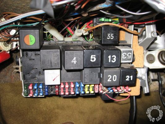
(the above pic being extracted from kae_relais_01.pdf).
But my reference clearly shows that upper RH "gap" in the 87 circuit to be a fuse. (If you can replace that fuses, then fine. If not, why replace a relay because of a blown fuse? I'd rather omit the fuse and blow the relay! But I can see a safety argument - after all, it's not as if anyone could bypass that fuse by jumpering 30 to 87... [yes, I am mocking that design... I mean, I am merely preempting the common shallow replies I often get.])
Incidentally, the above reference is a Mitchell "Electronic Fuel Injection; Imported Cars, Light Trucks & Vans", Edition 1 (1989). (That was one of my "I don't need but what a great price!" purchases at a market that years later I found to be almost priceless. Yay! FTW.)
You may not have other fuel cuts. IMO that is not required for EFI because as soon as the pumps stops, the fuel pressure & flow stops. (Or very quickly thereafter, ignoring surge tanks.) Though maybe as a way of sealing the fuel tank in case of a line rupture...
But that "engine is running" signal - whether from an alternator L/D+ circuit or spark sensor etc - it often used for fuel pumps, electric chokes for carbies, and early ejection seats (till they figured out engine running could still be in the shed; later seats were speedo linked so you had a better chance of NOT still being in the home garage, hence it was statistical whether you were killed being ejected into a tunnel, bridge or car-park roof, or being run over by the following truck or evil spies).
Anyhow, maybe I do elaborate somewhat excessively, but however it is done (alternator, airflap, spark), it is a perfect signal for many systems (fuel pumps, battery isolators, etc).
IMO that KEA 3.300.210 is easily FUNCTIONALLY replaced - eg SPST relay with external fuse, and either and external spark sensing circuit, else a diode-OR'd (joining) of D+ & crank signals.
BTW - D+ is often a mere spade connector. Do not confuse D+ (or L = charge Light) with the heavy B or B+ alternator output (to battery +12V and the vehicle). Re- or dis-connecting B/B+ is a totally different consideration!
   
It's been a while since I discussed EFI.
But yes, I enjoy my 1960s vintage pushrod-engined CARBY vehicle. (LOL!) (Though I am considering converting my next engine(s) to EFI...)
howie ll 
Pot Metal - Posts: 16,466
Pot Metal spacespace
Joined: January 09, 2007
Location: United Kingdom
Posted: September 06, 2011 at 5:45 AM / IP Logged  
We called your Holden an Isuzu Pizza Peter damage a relay by crossing meter leads? -- posted image.
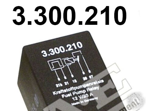
Surely we're talking about the primer circuit here and do NOT swap a standard SPST or SPDT relay for a 31b, the 31b denotes a second ground (earth) switch.
Do you think UK or US English will ever unify earth and ground as used in auto electrics?
vayankee 
Member - Posts: 28
Member spacespace
Joined: September 04, 2011
Location: Virginia, United States
Posted: September 06, 2011 at 8:52 AM / IP Logged  

In one way we in the US are fortunate that we still get truly imported cars, but for car enthusiasts, not ever seeing a Holden or other such on the roads is very sad.

And yes, I will stay with the VW-designated relay. But the discussion of alternatives has been stimulating, as long as I can follow it!

Finally, you wrote: "Do you think UK or US English will ever unify earth and ground as used in auto electrics?" Not bloody likely on this side of the Atlantic pond, while the media here is heavy with flat-earth type thinking, or arguments without any grounds (Pardon my politics).

Page of 3

  Printable version Printable version Post ReplyPost New Topic
You cannot post new topics in this forum
You cannot reply to topics in this forum
You cannot delete your posts in this forum
You cannot edit your posts in this forum
You cannot create polls in this forum
You cannot vote in polls in this forum

  •  
Search the12volt.com
Follow the12volt.com Follow the12volt.com on Facebook
Saturday, June 1, 2024 • Copyright © 1999-2024 the12volt.com, All Rights Reserved Privacy Policy & Use of Cookies
Disclaimer: *All information on this site ( the12volt.com ) is provided "as is" without any warranty of any kind, either expressed or implied, including but not limited to fitness for a particular use. Any user assumes the entire risk as to the accuracy and use of this information. Please verify all wire colors and diagrams before applying any information.

Secured by Sectigo
the12volt.com spacer
Support the12volt.com
Top
the12volt.com spacer