the12volt.com spacer
icon

schematic proof read


Post ReplyPost New Topic
< Prev Topic Next Topic >
--weezl-- 
Member - Posts: 45
Member spacespace
Joined: September 12, 2011
Location: Alberta, Canada
Posted: September 12, 2011 at 8:25 PM / IP Logged  
hey, i'm new here, hoping to get a little bit of help on a diagram i drew up today, basically, what i'm doing is wiring my truck up with amber safety lights, the legal aspect has all been taken care of, so no worries there, the product i'm making my own kit out of several random items from different places, the main part that needs to be known to you guys, is the module, for all intents and purposes, the "module" is a wig wag module... if anyone has used this particular one, please let me know what you have found, and if you have used it, please let me know how the 3rd output wire works on the patterns... all of the patterns they show are an a/b system, which would have 2 outputs... idk... here's the schematic though:
now before you ask, the modules aren't all that cheap, so to keep my costs down, i'm using one, but i need to be able to independently control the front and rear of the truck's lights, which is the whole purpose of this schematic... the only thing i think i might have made a mistake on, is the directionality of the diodes (both LED and normal) that is one thing i'm not concerned about, but i think they are in the correct way...
schematic proof read -- posted image.
no signature needed
--weezl-- 
Member - Posts: 45
Member spacespace
Joined: September 12, 2011
Location: Alberta, Canada
Posted: September 12, 2011 at 8:29 PM / IP Logged  
doesn't appear my picture worked... here's a photobucket version...
schematic proof read -- posted image.
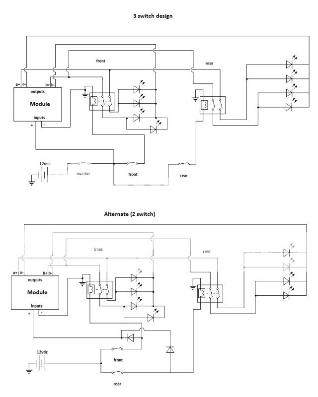
additionally, the flasher module i'm looking at is this one (i am not promoting the brand at all, merely asking for advice on wiring, and products http://www.ebay.ca/itm/4x-4W-LED-WHITE-Flash-Strobe-Light-Headlight-USA-SELLER-/400225987719?pt=Motors_Car_Truck_Parts_Accessories&hash=item5d2f53ec87
no signature needed
oldspark 
Gold - Posts: 4,913
Gold spacespace
Joined: November 03, 2008
Location: Australia
Posted: September 13, 2011 at 3:43 AM / IP Logged  
The diodes look ok, but the power diodes in the alt 2-switch version will have to be high current, else energise a power relay.
I suspect that flash-strobe is christmas-tree lighting circuit.
And handling 26 globes (meaning of the 21W variety) is a lot of LEDs! (IE - a single 12V LED string is typically 0.3W.)
--weezl-- 
Member - Posts: 45
Member spacespace
Joined: September 12, 2011
Location: Alberta, Canada
Posted: September 13, 2011 at 11:47 AM / IP Logged  
Thanks for the reply, the module I'm using is designed to run 27 4w led headlight bulbs.
Is there a simpler or better way to wire this up, that you can see at all?
Thanks for the reply btw!
no signature needed
oldspark 
Gold - Posts: 4,913
Gold spacespace
Joined: November 03, 2008
Location: Australia
Posted: September 13, 2011 at 1:23 PM / IP Logged  
Better? There are several options depending on preference - ie, using DPST switches instead of relays, though I prefer relays - especially if they are high current (~10A etc) or remote.
I reckon the lower diagram with ordinary diodes (IN4004 etc) from the front & rear switches that energise an SPST relay to provide power to the module input+.
And a fuse from the battery of course.
PS - actually I don't see the need to switch the -ve (else +ve) of the LEDs - hence just SPST relays.
--weezl-- 
Member - Posts: 45
Member spacespace
Joined: September 12, 2011
Location: Alberta, Canada
Posted: September 15, 2011 at 11:27 PM / IP Logged  
oldspark, i'm not quite following you there... basically, there are 4 wires from the module, that are going to the front leds, 2 for each set of leds, these 2 sets MUST be on separate circuits, otherwise i won't get the wigwag pattern that the module provides (among other patterns) so i would need 2 spst relays, per side, 4 total, for the 4 separately controlled lights (either controlled by me, or the module)
the switches i'm using are a 2 position on-on push button dpst switch, with LED indicator, (8 leads on the back)and i already have them, and i'm currently working on the bezel they will sit into, have about 10 hours into it so far, made out of polycarbonate...
what a friend of mine suggested, which i might look into down the road, is a 4 position switch, off, front, back, front & back... though i don't really like that idea as much as the 2 separate switches... the 3 individual switches seems a little cumbersome, the more i think about it, and takes up an unnecessary switch location, which i am sure i can find a use for...
as it is i've got locations for 5 switches, 1 will be for my ABS cancel, 2 will be for these lights, and 1 will be for my driving lights (2, big ass 100 watt halogens in the grill)
no signature needed
oldspark 
Gold - Posts: 4,913
Gold spacespace
Joined: November 03, 2008
Location: Australia
Posted: September 16, 2011 at 12:58 AM / IP Logged  
idiot oldspark who wishes to withdraw his former wrote:
PS - actually I don't see the need to switch the -ve (else +ve) of the LEDs - hence just SPST relays.
WITHDRAWN!!! See "FYI - my former reply opening:" below for a laugh!
As to your switches, in your case I'd say stick with it (with 10 hours work... It's always the "simple" harware fitment that takes eons!).
But in ANY case, I too prefer 2 switches rather than a 4-position switch. IMO - that is good design. [IE - simpler, independent, still half a circuit if one switch fails, and usually no need to check which position the switches are in (especially if paddle switches, ie - if not direcly looking). That's unless space was at a premium.]
With the 3rd switch, I think powering off the 2 existing switches is better AND easy - just the 2 diodes and an extra SPST relay. I prefer relays to switches anyhow if switching above a few Amps.   
Using your lower diagram, the two power diodes between the switches and the module's +12V supply (input) can be reduced to small diodes (eg, common 1A 1N400x series - IN4004 etc, instead of BIG diodes to handle the full module current, though they can also be used), and connected to the extra relay's coil (86, with 85 to GND). Its contacts (30 & 87) are inserted between the module + input and the batery supply to the switches.
IE - the diodes power the relay coil. The +12V module input is connected to 87 and its power (30) is takne from the switch +12V input.
And the lot shoud be protected by a fuse (or maybe self-resetting ciruit breaker; ~$8 for up to 50A capacity) between from the battery +12V.
Actually the last is merely a conversion from using high-current diodes to low-current diodes and a relay. That is often used for polarity protection - eg, car EMS, and any system that is at risk from incorrect polarity connections.   
So, other than my last "big to small" diode conversion, I have done nothing to change your 2nd/lower diagram (which IMO is by far the preferred solution. If curcuit isolation is ever required, simply pull the (not shown) fuse).   
FYI - my former reply opening:
Yes, they are on 2 separate circuits. Hence only 2 breaks are required - not 4 as you have.   Different if they were mutliplexed, but that's a totally different solution anyhow.    I thought I may have misread your diagram(s), but no - I think I'm still consistently sane (or insane).   To simplify in the active/closed circuit... No, YOU ARE RIGHT. It is "4 circuits" - they are multiplexed - each b outout goes to each a output.
See - even idiots like me get (very) confused and get things wrong.
It also shows (IMO) the need for a scribble pad sketch rather than a "head redraw" - though why my first 2 head jobs didn't work but the 3rd did (so to speak...) leaves me in my usual state of bewiderment.
& Hey - thanks! New name proposal - idiots like me - that could end my jealousy directed at i am an idiot. Though others hereon might take offence...
--weezl-- 
Member - Posts: 45
Member spacespace
Joined: September 12, 2011
Location: Alberta, Canada
Posted: September 17, 2011 at 3:11 AM / IP Logged  
lol, ok, so you are thinking something like this (with the spst relay) i was originally thinking you meany use spst instead of the dpst relays! lol
schematic proof read -- posted image.
ok, additional question, i want the brake lights to flash along with the led strobes, so here's the situation i'm thinking is going to come up, right now, none of this hardware, except for the top switch exists, it's all new parts that are going to be coming... i'm also not sure if it is a switched ground, or switched positive... i have a set here right now that are a switched ground, which makes me worry a little...
schematic proof read -- posted image.
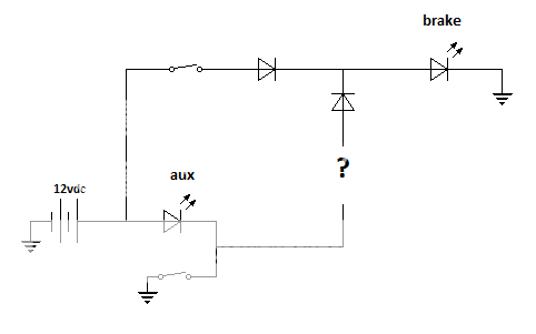
essentially, the aux light should be looked at as an LED strobe, and i want the brake light to strobe on, at the same time as the aux (not an issue if the brakes over ride it)
this same problem persists with my reverse lights, with how i want to wire them up... what do i put in place of the question mark, that will be able to keep up with the fast strobing? i could use a NO relay with constant power, but i can't see the relay lasting very long with the strobing effect...
no signature needed
--weezl-- 
Member - Posts: 45
Member spacespace
Joined: September 12, 2011
Location: Alberta, Canada
Posted: September 17, 2011 at 3:13 AM / IP Logged  
should have mentioned, that when this project gets done, every light on the exterior of the truck, will be LED, so there won't be any issues with bulbs not keeping up with the flashing, or burning out or anything...
no signature needed
--weezl-- 
Member - Posts: 45
Member spacespace
Joined: September 12, 2011
Location: Alberta, Canada
Posted: September 17, 2011 at 3:43 AM / IP Logged  
sorry to keep posting, by my math, the entire setup, should be drawing about 2.8a on the lights, maybe another .5 on the module, so 3.3 amps?
if i were to do it completely relay-less, i would need 2 tpst switches, wouldn't i? do they even make triple pole switches?
i think with the relitvely low current draw, (3.3 amps or so) i should be good with just the 2 relays, 2 switches, 2 power diodes... the switches i have are rated at 3a 220vac, but the LED in them is 12vdc...
not to mention there will never be that full 3.3 amps running through the switch at one time... though i don't know exactly what my tail lights draw... i could look that up though... i know it's less than stock, because they come with load equalizers...
front would be... 24w, so 2a, and the rear has about 10-11 plus the brake lights... lets say high side, brake lights are 7w each, 25ish w on the back, so another 2 amps or so... each switch would only be looking at a 2 amp load, which should be well within range, not to mention these switches SHOULD have a safety factor, right?
no signature needed
Page of 3

  Printable version Printable version Post ReplyPost New Topic
You cannot post new topics in this forum
You cannot reply to topics in this forum
You cannot delete your posts in this forum
You cannot edit your posts in this forum
You cannot create polls in this forum
You cannot vote in polls in this forum

  •  
Search the12volt.com
Follow the12volt.com Follow the12volt.com on Facebook
Wednesday, April 17, 2024 • Copyright © 1999-2024 the12volt.com, All Rights Reserved Privacy Policy & Use of Cookies
Disclaimer: *All information on this site ( the12volt.com ) is provided "as is" without any warranty of any kind, either expressed or implied, including but not limited to fitness for a particular use. Any user assumes the entire risk as to the accuracy and use of this information. Please verify all wire colors and diagrams before applying any information.

Secured by Sectigo
the12volt.com spacer
Support the12volt.com
Top
the12volt.com spacer