


external power supply on conversion van
Home /
the12volt's Install Bay /
General Discussion / external power supply on conversion van ( Topic Closed)


Posted: October 10, 2011 at 10:12 PM / IP Logged


Posted: October 10, 2011 at 10:39 PM / IP Logged
Posted: October 11, 2011 at 1:45 AM / IP Logged
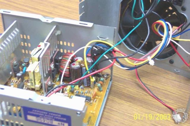 ... where the chip (IC) on the mid-RHS (partly obscured by the case) might be the SMPS chip we are looking for. (It's the black "beetle" with 2 of its 14 legs visible.)
And that one still has its numbers!
But it might be another chip elsewhere...
So, can you see the chips in yours? And post the numbers? (probably starting with letters like MC, ICL, T etc; the "lowest" numbers are usually date codes....)
As to your 11.57, 11.86 & 12.6V outputs - yep, that's a typical range.
The 5V definitely has to be within +/-10% (4.5V to 5.5V) because more or less can damage traditional logic chips (TTL etc).
12V is often for fans and motors (disks) which are not that critical.
But you see the range - and you want to convert from (say) 11.5V to 13V - 14V. That's a 1.5V to 2.5V increase. If that's resistive, it'll get hotter than the diodes (ie, 1.5V @ 20A = 30W etc).
So we find the feedback "loop", splice in a few diodes (can add a switch to short some of them out to drop the voltage) and you set or dial whatever voltage you want. (Well, in 0.6V steps unless you use Schottky diodes or other tricks.)
... where the chip (IC) on the mid-RHS (partly obscured by the case) might be the SMPS chip we are looking for. (It's the black "beetle" with 2 of its 14 legs visible.)
And that one still has its numbers!
But it might be another chip elsewhere...
So, can you see the chips in yours? And post the numbers? (probably starting with letters like MC, ICL, T etc; the "lowest" numbers are usually date codes....)
As to your 11.57, 11.86 & 12.6V outputs - yep, that's a typical range.
The 5V definitely has to be within +/-10% (4.5V to 5.5V) because more or less can damage traditional logic chips (TTL etc).
12V is often for fans and motors (disks) which are not that critical.
But you see the range - and you want to convert from (say) 11.5V to 13V - 14V. That's a 1.5V to 2.5V increase. If that's resistive, it'll get hotter than the diodes (ie, 1.5V @ 20A = 30W etc).
So we find the feedback "loop", splice in a few diodes (can add a switch to short some of them out to drop the voltage) and you set or dial whatever voltage you want. (Well, in 0.6V steps unless you use Schottky diodes or other tricks.)Posted: October 11, 2011 at 2:16 AM / IP Logged
Posted: October 11, 2011 at 2:32 AM / IP Logged
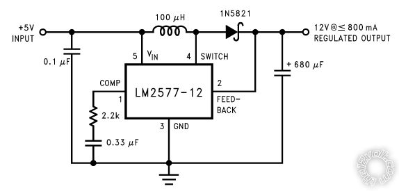 Think of the LM2577 as being your entire PSU for 12V except for a few components - like the 100uH coil (transformer) and the 0.1uF & 680uF input & output filter capacitors and a diode and RC crap (2.2k & 0.33uF).
It has 5V input which it converts to 12V (using magic and that transformer - aka coil or choke).
How does it know it is outputting 12V? It has a FEEDBACK or SENSE terminal (#2). If the output drops, pin #2 drops and the "magic box" increases output voltage etc. That's called regulation.
What happens if we insert a diode between the output and pin #2? Assuming the correct orientation (ie, the diode's arrow head points from the Output to #2 which means the diode's LINE-end is towards pin #2), then there is a 0.6V drop.
So output is 12V, pin #2 is 12V - 0.6V - 11.4V which is not its programmed 12V so it bumps the output 0.6V. (Hence #2 = out = 12.6 less diode 0.6V = 12.0V so all is cool.)
Same for 3 x 0.7V diodes = 2.1V => output is (12V + 2.1V =) 14.1V.
Too easy eh?
Look at most of the diagrams on that link.
Almost all have a FB = Feedback = S = Sense terminal.
Some are not direct like the LM2577-12 above - they go through a resistive voltage divider (2 resistors with or without a trim-pot (variable resistor)) so that the output voltage can be adjusted. (The LM2577-12 is a fixed 12V output, but we can trick it to go higher as I described - just as we can trick most car alternators to increase their output voltage.)
Not that the voltage divider crap matters. All we have to do is insert diodes between the actual output and the "top" of the feedback link.
However, if we find the feedback resistors, we could instead add a trim-pot so you can fully adjust the output voltage.
Maybe the PSU even has a trimpot that has been locked in place with nail-polish etc!
If the 5V rail is similar, we can boost that too. (Main danger there is its output filter capacitors that are likely to be 5V or 10V rating - not the 16V or 25V required for 12-14V etc.)
Are you getting a slightly warn feeling? If it's a short-circuit warmth, that's ok. This is a lot in one go.
But hopefully you might see that most of those diagrams are all the same as the "simple" one above - an input and output voltage either side of a coil/inductor, and some box etc that somehow controls that "coil converter". Oh - and the voltage feedback. The rest doesn't matter - they only add that to prevent simpletons like us thinking we understand them. (At least for now...)
Think of the LM2577 as being your entire PSU for 12V except for a few components - like the 100uH coil (transformer) and the 0.1uF & 680uF input & output filter capacitors and a diode and RC crap (2.2k & 0.33uF).
It has 5V input which it converts to 12V (using magic and that transformer - aka coil or choke).
How does it know it is outputting 12V? It has a FEEDBACK or SENSE terminal (#2). If the output drops, pin #2 drops and the "magic box" increases output voltage etc. That's called regulation.
What happens if we insert a diode between the output and pin #2? Assuming the correct orientation (ie, the diode's arrow head points from the Output to #2 which means the diode's LINE-end is towards pin #2), then there is a 0.6V drop.
So output is 12V, pin #2 is 12V - 0.6V - 11.4V which is not its programmed 12V so it bumps the output 0.6V. (Hence #2 = out = 12.6 less diode 0.6V = 12.0V so all is cool.)
Same for 3 x 0.7V diodes = 2.1V => output is (12V + 2.1V =) 14.1V.
Too easy eh?
Look at most of the diagrams on that link.
Almost all have a FB = Feedback = S = Sense terminal.
Some are not direct like the LM2577-12 above - they go through a resistive voltage divider (2 resistors with or without a trim-pot (variable resistor)) so that the output voltage can be adjusted. (The LM2577-12 is a fixed 12V output, but we can trick it to go higher as I described - just as we can trick most car alternators to increase their output voltage.)
Not that the voltage divider crap matters. All we have to do is insert diodes between the actual output and the "top" of the feedback link.
However, if we find the feedback resistors, we could instead add a trim-pot so you can fully adjust the output voltage.
Maybe the PSU even has a trimpot that has been locked in place with nail-polish etc!
If the 5V rail is similar, we can boost that too. (Main danger there is its output filter capacitors that are likely to be 5V or 10V rating - not the 16V or 25V required for 12-14V etc.)
Are you getting a slightly warn feeling? If it's a short-circuit warmth, that's ok. This is a lot in one go.
But hopefully you might see that most of those diagrams are all the same as the "simple" one above - an input and output voltage either side of a coil/inductor, and some box etc that somehow controls that "coil converter". Oh - and the voltage feedback. The rest doesn't matter - they only add that to prevent simpletons like us thinking we understand them. (At least for now...)
Posted: October 11, 2011 at 2:40 AM / IP Logged
Posted: October 11, 2011 at 3:02 AM / IP Logged
Posted: October 11, 2011 at 3:29 AM / IP Logged
Posted: October 11, 2011 at 12:40 PM / IP Logged
Posted: October 11, 2011 at 3:35 PM / IP Logged
 Printable version
| You cannot post new topics in this forum You cannot reply to topics in this forum You cannot delete your posts in this forum You cannot edit your posts in this forum You cannot create polls in this forum You cannot vote in polls in this forum |

| Search the12volt.com |
Follow the12volt.com 
Wednesday, April 1, 2026 • Copyright © 1999-2026 the12volt.com, All Rights Reserved • Privacy Policy & Use of Cookies

Wednesday, April 1, 2026 • Copyright © 1999-2026 the12volt.com, All Rights Reserved • Privacy Policy & Use of Cookies
Disclaimer:
*All information on this site ( the12volt.com ) is provided "as is" without any warranty of any kind, either expressed or implied, including but not limited to fitness for a particular use. Any user assumes the entire risk as to the accuracy and use of this information. Please
verify all wire colors and diagrams before applying any information.
