the12volt.com spacer
icon

need advice on power door lock wiring


Post ReplyPost New Topic
< Prev Topic Next Topic >
xcalibr1 
Member - Posts: 25
Member spacespace
Joined: January 30, 2008
Location: United States
Posted: October 13, 2011 at 10:41 PM / IP Logged  
I have a 91 Escort GT that I added factory power door locks to. I am installing a remote start system that has security and door lock features. Im not wiring any of the security (why bother on a 91 Escort? LOL) but I want to use the keyless entry function. I have added a lock actuator to the drivers door as this unique low end factory system does not originally use one. I cannot find any door lock wiring that matches this system as it different. It does not use a keyless remote or even a switch inside the car. When you lift up on the lock knob or turn the key in the door lock it throws a switch to either LOCK or UNLOCK depending on what you are doing. This send current to either the LOCK wire or the UNLOCK wire which in turn goes to a solid state relay that sends a single short pulse to the door lock actuator to either lock or unlock. So one of the wires always has current to it but the solid state relay only outputs that short pulse and then thats it. My remote start kit puts out a negative signal for lock or unlock. I just cant figure out the proper way to wire relays into this system. I really dont want to get into using diodes if I dont have to as I never did that. I think the lock actuators just get the power and ground reversed for lock or unlock. But if I have the relays send power to the output side of the solid state relay Im afraid it would back feed into the relay and mess it up. Can anyone give me some insight and tell me how to correctly wire this setup so I can use the keyless entry feature? Am I correct in assuming that I dont need to wire the starter kill relay as well as it is for the security system which Im not using?
howie ll 
Pot Metal - Posts: 16,466
Pot Metal spacespace
Joined: January 09, 2007
Location: United Kingdom
Posted: October 14, 2011 at 4:59 AM / IP Logged  
The actuator in your driver's door should have 5 wires. As a guess black, brown, white, green and blue.
The white and brown are the triggers, neg pulse to either will lock and unlock the doors respectively.
If YOUR colours are different, please let me know.
xcalibr1 
Member - Posts: 25
Member spacespace
Joined: January 30, 2008
Location: United States
Posted: October 14, 2011 at 10:53 AM / IP Logged  
The actuator is only 2 wires. This is a different system than most Im sure. As I said, its a low end power door lock system originally. It only uses a RH actuator as you are manually unlocking the drivers door with either the key or if you are inside you are pulling up on the door lock knob. Either of these actions causes the power to either the LOCK or UNLOCK input of the solid state relay and it sends power to the RH actuator. You can easily tandem in a LH actuator as I have done which serves absolutley no purpose unless you have a keyless remote system added on. There is no actual switch in the doors to lock or unlock. need advice on power door lock wiring - Last Post -- posted image.
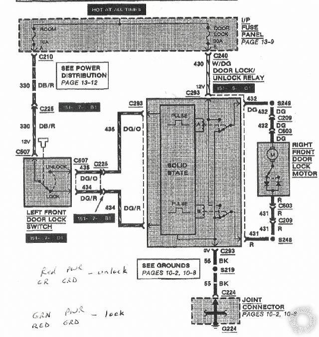
This is the wiring schematic. The switch in the LH door latch sends constant power to either the LOCK or UNLOCK input of the solid state relay which gives a pulse to either the lock circuit or unlock circuit. Simple enough but just dont know how to tie into that with this system so it doesnt backfeed into the relay and mess something up.
howie ll 
Pot Metal - Posts: 16,466
Pot Metal spacespace
Joined: January 09, 2007
Location: United Kingdom
Posted: October 14, 2011 at 12:56 PM / IP Logged  
Use this method, requires two relays:-
ford.bmp
xcalibr1 
Member - Posts: 25
Member spacespace
Joined: January 30, 2008
Location: United States
Posted: October 14, 2011 at 1:14 PM / IP Logged  
But wouldnt this method backfeed into the solid state relay and possibly cause damage? I just want to make sure Im not gonna burn something out.
howie ll 
Pot Metal - Posts: 16,466
Pot Metal spacespace
Joined: January 09, 2007
Location: United Kingdom
Posted: October 14, 2011 at 1:34 PM / IP Logged  
No, not at all but to protect your R/S place two diodes inline on the lock wires from the R/S to the relays, also an actuator in the driver's door can be paralleled off the existing motor wires to give you full locking. This system is identical to Volvos an others in the late 80s.
See diagram:- 21B_ford.bmp
Just to be difficult, wire your locks to relays to add motor, see the relay diagrams on this site and simply add one actuator to the driver's door, this should have the effect of locking and unlocking the other door if the lock button already does so, trouble is it's six of one and a half dozen of the other, same parts etc.
xcalibr1 
Member - Posts: 25
Member spacespace
Joined: January 30, 2008
Location: United States
Posted: October 14, 2011 at 1:40 PM / IP Logged  
I didnt want to get into diodes as I never had any experience with them. I wanted to try and keep it simple without them.

Sorry, you can NOT post a reply.
This topic is closed.

  Printable version Printable version Post ReplyPost New Topic
You cannot post new topics in this forum
You cannot reply to topics in this forum
You cannot delete your posts in this forum
You cannot edit your posts in this forum
You cannot create polls in this forum
You cannot vote in polls in this forum

  •  
Search the12volt.com
Follow the12volt.com Follow the12volt.com on Facebook
Friday, April 26, 2024 • Copyright © 1999-2024 the12volt.com, All Rights Reserved Privacy Policy & Use of Cookies
Disclaimer: *All information on this site ( the12volt.com ) is provided "as is" without any warranty of any kind, either expressed or implied, including but not limited to fitness for a particular use. Any user assumes the entire risk as to the accuracy and use of this information. Please verify all wire colors and diagrams before applying any information.

Secured by Sectigo
the12volt.com spacer
Support the12volt.com
Top
the12volt.com spacer