the12volt.com spacer
icon

bulb out indicator


Post ReplyPost New Topic
< Prev Topic Next Topic >
oldspark 
Gold - Posts: 4,913
Gold spacespace
Joined: November 03, 2008
Location: Australia
Posted: December 30, 2011 at 1:25 AM / IP Logged  
Ah - you're using the LT1637 version.
That particular LT1637 circuit is only suitable for similar Comparators "... part substitutions are discouraged". It's a somewhat specialized circuit, hence the 3V etc.
I thought you were using the "4 resistor" twin input type, ie - the same bulb & 0.5R for the + input, but the 0.5R goes to +12V (bulb power) - ignore the rest.
The inverting (-) input is connected to the junction of a resistor to the LM339 or equivalent's +12V, and a trim- or variable-pot (pot = potentiometer) to GND.
The trimpot is adjusted for the bulb(s) to light the LED connected from LM339 output thru a resistor to +12V. (ie, LED-on with one bulb removed, LED-off with all bulbs working.)     
I was about to upload a pic but it's a modification of a copyrighted diagram (namely R.Paisley's - half of the "Photocell Circuits" Photocell Circuits Schematic at http://home.cogeco.ca/~rpaisley4/Comparators.html... Great stuff! Seen ~rpaisley4/CircuitIndex.html?).
And I thought wiki had a similar pic...
urhottboy85 
Member - Posts: 20
Member spacespace
Joined: July 25, 2011
Posted: January 02, 2012 at 7:28 PM / IP Logged  
Actuslly I was just following the diagram you posted...but instead I have the 12v source coming in to a 5v regulator...so actually I'm basically following the 4 resistor type...and I have a 100 ohm resistor for the leds so the 5v will power them so I guess following the diagram is ok for the way I have it set up
oldspark 
Gold - Posts: 4,913
Gold spacespace
Joined: November 03, 2008
Location: Australia
Posted: January 03, 2012 at 12:02 AM / IP Logged  
Ok - the pic below is the circuit... (Redrawn, but still with thanks to R. Paisley.)
Note that no protection circuitry (diodes) is shown. This is just the basic circuit...
bulb out indicator - Page 4 - Last Post -- posted image.
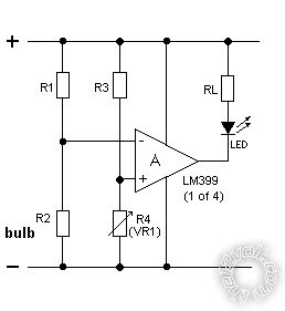
R2 is the bulb and R1 the low value (aka power) resistor (which may need to be bigger than 1/2W for some values & bulbs).
The tested bulb(s) R2 vary from approx 20 Ohm (7W taillight) to 3 Ohm (2x 23W stop) or 1.5 Ohm (4x stop).
The voltage at the power-resistor/bulb junction (R1-R2 & "-" input) has to match the the voltage at the R3-R4 junction (+ input) for the comparator to be at its switching point.
Hence adjust R4 so the LED just turns off with the bulbs as normal (engine off is fine - no voltage regulation is involved hence circuit remains "balanced").
The biggest voltage drop across the bulb's power resistor R1 is when all bulbs are operating. (ie, V=IR so V is max when current I is max, ie, the most bulbs.)
Whilst R1's voltage drop exceeds that of R3, the inverting or "-" input voltage is LOWER than the non-inverting or "+" input, and hence the comparator (output) is off (ie, floating).
If a bulb blows, the current should be lower (or nil) thru R1 so that - subtracted from the +12V rail - means that the "-" voltage rises and should be above the "+" input, hence the comparator turns on - ie, the output connects to 0V/GND and can sink 16mA, hence R-LED RL should be ~12V/0.017A = 706 Ohms => 820 Ohms (1/2W though 1/4W may be ok).
IE - the comparator turns on a LED connected through an 820 Ohm (1/2W) resistor to +12V. The 820R limits the (LED) current to under 16mA to protect the LM339 output.
BTW - I chose 10k for the R4 trimpot as it's a common size; not too much current but enough to generally swamp car noise.
I also chose the voltage drop across R1 & R3 to be 0.5V, though a mere 0.05V should also work - but I'm unsure of comparator behavior with near +V inputs - it should IMO be ok; but most comparators compare voltages closer to 0V/GND.   
One problem with a regulated supply is that the Comparator and R3 & R4 have constant voltage but the bulb input does not since it is powered from the vehicle's +12V and hence can vary from (say) 12V to 14.5V, or 20%.
That shouldn't be a problem for single & dual bulbs, but may be a problem for 4 bulbs depending on trimpot sensitivity. (Sensing 4 bulbs means sensing a 25% change (1 of 4), but the signal varies 20%, hence only a5% adjustment tolerance".
If you include cranking - hence 9V to 14.5V or 45%. So sensing 2 bulbs (50%) is possible...)
The unregulated circuit doesn't have that issue - as the vehicle voltage varies, so do the "reference" points (ie, BOTH the + & - input voltages react similarly to voltage changes so it shouldn't false-switch).
I'd forgotten that Op-Amps and Comparators handle up to 35V supplies and hence can be used in "raw" +12V car environments (excluding spike protection (zenor & resistor, & run LED/load from raw +12V.) Good-bye evil voltage regulators and voltage restrictions.   
urhottboy85 
Member - Posts: 20
Member spacespace
Joined: July 25, 2011
Posted: January 03, 2012 at 12:27 AM / IP Logged  
Ok so what's the diagram on the first page? I ashtray have that one built and now I have to redo the whole thing? I'm going off of 5v not 12 anymore
oldspark 
Gold - Posts: 4,913
Gold spacespace
Joined: November 03, 2008
Location: Australia
Posted: January 03, 2012 at 12:54 AM / IP Logged  
oldspark wrote:
That's just an example using a "high spec" comparator...
And later I refer to the circuit type above... "...see the "Comparator Operation" section a few screens down...", and the LM339. And "Maybe the type of circuit shown under Bristolwatch/Paisley's "Voltage Window Detector Circuit" ... is what you want?".   
But I thought I had posted "that" diagram. It wasn't until Dec30 I realized I hadn't - I did sometime after Nov30, but it either got removed with the spam posted before, else it got lost en-route (it happens; but rarely!).
And I thought that was the 4-resistor circuit you were constructing, and you got a quad comparator hence NOT constructing the sample LT1637 circuit (cannot substitute random components).
Page of 4

Sorry, you can NOT post a reply.
This topic is closed.

  Printable version Printable version Post ReplyPost New Topic
You cannot post new topics in this forum
You cannot reply to topics in this forum
You cannot delete your posts in this forum
You cannot edit your posts in this forum
You cannot create polls in this forum
You cannot vote in polls in this forum

  •  
Search the12volt.com
Follow the12volt.com Follow the12volt.com on Facebook
Thursday, May 16, 2024 • Copyright © 1999-2024 the12volt.com, All Rights Reserved Privacy Policy & Use of Cookies
Disclaimer: *All information on this site ( the12volt.com ) is provided "as is" without any warranty of any kind, either expressed or implied, including but not limited to fitness for a particular use. Any user assumes the entire risk as to the accuracy and use of this information. Please verify all wire colors and diagrams before applying any information.

Secured by Sectigo
the12volt.com spacer
Support the12volt.com
Top
the12volt.com spacer