the12volt.com spacer
icon

flashlogic wiring


Post ReplyPost New Topic
< Prev Topic Next Topic >
wyciwug 
Copper - Posts: 156
Copper spacespace
Joined: February 08, 2008
Location: Virginia, United States
Posted: December 01, 2011 at 1:00 PM / IP Logged  
Hello
I got the RS4103 hooked up. I have question about hooking up the FlashLogic FLC-AL. Had it flashed for used with 2003 Toyota Sequoia
I figured this is type 1 installation. I want to use DBI port to connect to the RS. However, Do i still use other wires as well? Such as WHITE/ black, WHITE/ red, orange-amp, pink/black, Pink, Blue/Red, GREEN/ Red, Gray/Red. I know that if I used DBI, i do not need to use Blue/white, Black, and 12V Red wires.
And it said 1x Diode required? Where would I use that in?
dcd
dasbogie 
Silver - Posts: 514
Silver spacespace
Joined: September 30, 2006
Location: Pennsylvania, United States
Posted: December 01, 2011 at 2:40 PM / IP Logged  
basically the only thing dbi is saving you is power,ground, and status.  every solid black line must be hardwired.  
Advanced
mxxmikexx 
Silver - Posts: 796
Silver spacespace
Joined: September 18, 2002
Location: United States
Posted: December 02, 2011 at 10:16 PM / IP Logged  
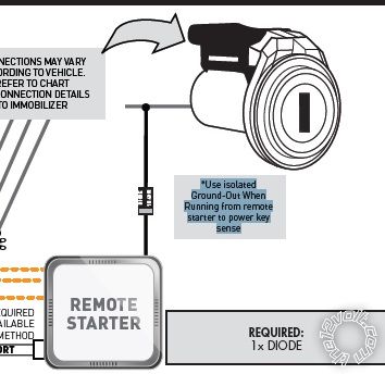
*Use isolated
Ground-Out When
Running from remote
starter to power key
sense
TAKE YOUR GROUND OUTPUT WHILE RUNNING FROM YOUR REMOTE START, INSTALL THE DIODE WITH THE BAND FACING REMOTE STARTER, CONNECT OTHER SIDE TO KEYSENSE WIRE IN CAR.flashlogic wiring -- posted image.
Mike Battaglia
Specialized Car Audio
Bensenville IL 60106
wyciwug 
Copper - Posts: 156
Copper spacespace
Joined: February 08, 2008
Location: Virginia, United States
Posted: December 08, 2011 at 6:49 AM / IP Logged  

Hello Mike

Thanks for awesome diagram for using the diodes.  However, i still have a question.

I looked at Type 1 wiring diagram for the sequoia.  I used W2W connections type.  I connected the "ground-out when running" from the remote start to the blue/white wire on 4pin connector of the Flashlogic.  Then how can I use that same wire (Ground-Out when running) to connect to the keysense of the Vehicle?  Thanks!!!!

I am sure i did something wrong with this wire that causing the alarm to went off when RS now.  It worked for a week without setting off factory alarm but now it does.

dcd
Mike M2 
Platinum - Posts: 2,652
Platinum spacespace
Joined: June 29, 2005
Location: United States
Posted: December 08, 2011 at 8:31 PM / IP Logged  
You need to connect the keysense wire so that the factory alarm will disarm before it starts. It connects to the same blue/white GWR wire, but you need to diode isolate it.....
Mike M2
Tech Manager
CS Dealer Services
wyciwug 
Copper - Posts: 156
Copper spacespace
Joined: February 08, 2008
Location: Virginia, United States
Posted: December 30, 2011 at 8:36 AM / IP Logged  

hello Mike

The remote start works for a week without setting off the factory alarm.  But now it does it again.  I connected blue/white from the remote start to the diode with the band facing RS, then connect the other end of the diode to the keysense. 

I also connect that blue/white from the remote start to the Flash Logic wires as shown in the diagram.

Could that be the cause of the problem?  I uses one blue/white from the RS to connect to both flashlogic and keysense.  However, if it is the problem, why did it work for one week or two?  Thanks

dcd

Sorry, you can NOT post a reply.
This topic is closed.

  Printable version Printable version Post ReplyPost New Topic
You cannot post new topics in this forum
You cannot reply to topics in this forum
You cannot delete your posts in this forum
You cannot edit your posts in this forum
You cannot create polls in this forum
You cannot vote in polls in this forum

  •  
Search the12volt.com
Follow the12volt.com Follow the12volt.com on Facebook
Saturday, April 20, 2024 • Copyright © 1999-2024 the12volt.com, All Rights Reserved Privacy Policy & Use of Cookies
Disclaimer: *All information on this site ( the12volt.com ) is provided "as is" without any warranty of any kind, either expressed or implied, including but not limited to fitness for a particular use. Any user assumes the entire risk as to the accuracy and use of this information. Please verify all wire colors and diagrams before applying any information.

Secured by Sectigo
the12volt.com spacer
Support the12volt.com
Top
the12volt.com spacer