the12volt.com spacer
icon

2009-2011 Toyota Yaris Remote Starter Pictorial


Post ReplyPost New Topic
< Prev Topic Next Topic >
rhendy87 
Member - Posts: 7
Member spacespace
Joined: October 18, 2012
Location: Indonesia
Posted: October 21, 2012 at 8:41 AM / IP Logged  
i found the wire and the module is working just fine.
the fuel pump wire is more for the remote start thing.
thankss
jolietjim 
Member - Posts: 4
Member spacespace
Joined: December 28, 2009
Location: Illinois, United States
Posted: November 08, 2014 at 6:57 PM / IP Logged  
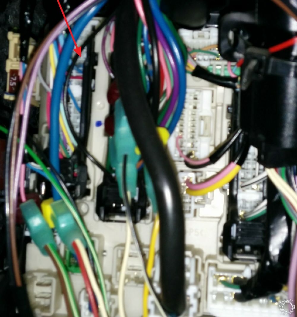
Seeing how the IG 1 & 2 on the ignition switch harness are small gauge wires would you recommend installing your remote start 12V constants on the large black main feed in the under dash fuse box or on the ignition switch connector wires?
kreg357 
Platinum - Posts: 7,783
Platinum spaceThis member has made a donation to the12volt.com. Click here for more info.spaceThis member has been recognized as an authority in Electrical Theory. Click here for more info.spaceThis member has been recognized as an authority in Mobile Security and Convenience. Click here for more info.spacespace
Joined: January 30, 2009
Location: Pennsylvania, United States
Posted: November 08, 2014 at 7:39 PM / IP Logged  
That is the way I usually do it.  Run the R/S's +12V constant input power feeds to the thick Black +12V constant wire at the fuse box.  While the ignition switch plug has a 25 Amp and a 15 Amp +12V constant wire, trying to correctly "load balance" the R/S's +12V input wires could be difficult and result in vehicle blown fuses.  Much safer to go to the thick Black wire.
Soldering is fun!
jolietjim 
Member - Posts: 4
Member spacespace
Joined: December 28, 2009
Location: Illinois, United States
Posted: November 08, 2014 at 7:58 PM / IP Logged  
Thank you for the fast reply, have a great weekend.
jgarcia1925 
Copper - Posts: 57
Copper spacespace
Joined: November 10, 2014
Location: Illinois, United States
Posted: November 11, 2014 at 1:17 PM / IP Logged  
hate to bring up more questions to this older thread, but im working on one of these soon. the 07 yaris that i will be doing the install has no power locks, and im adding those on, anyone have pictures of anybody who has done these before, they have cable locks which is why i ask, or any suggestions would be great. also, i dont think this will need any bypass since the keys are metal, but do we still need to hookup the keysense for anything?
the help would be great! thanks!
jesus
windog 
Member - Posts: 4
Member spacespace
Joined: September 30, 2009
Location: Manitoba, Canada
Posted: October 21, 2016 at 11:04 PM / IP Logged  
I have never seen a remote start installation requiring the information you are asking for. Why would you need oil control info for a simple install? is this some special equipment?
howie ll 
Pot Metal - Posts: 16,466
Pot Metal spacespace
Joined: January 09, 2007
Location: United Kingdom
Posted: October 27, 2016 at 5:59 PM / IP Logged  
Windog, some cheap and nasty products require oil pressure sensor to detect tach, very unreliable and if a prouct mentions it, avoid like the plague!
hoanayang 
Member - Posts: 7
Member spacespace
Joined: January 30, 2017
Location: California, United States
Posted: February 26, 2017 at 7:38 PM / IP Logged  
Thank you!
1. I want to connect to the horn, but I found I don't have pin 18 black wire. what should I do when I don't have that wire to split out?
2. My alarm has one wire needs to connect to the door sensor. However, I think yaris 2009 has 4 different wires for each door, pin 21, 24,5,and 20 (30 pins plug). How can I connect them to one wire only in the alarm system? Or I was looking at the wrong wire?
Thanks!
Camille
2009-2011 Toyota Yaris Remote Starter Pictorial - Page 3 -- posted image.
kreg357 
Platinum - Posts: 7,783
Platinum spaceThis member has made a donation to the12volt.com. Click here for more info.spaceThis member has been recognized as an authority in Electrical Theory. Click here for more info.spaceThis member has been recognized as an authority in Mobile Security and Convenience. Click here for more info.spacespace
Joined: January 30, 2009
Location: Pennsylvania, United States
Posted: February 27, 2017 at 7:19 PM / IP Logged  
Here are some other locations / possibilities for the Horn wire :
Audiovox :
Horn    LIGHT GREEN (-)      AT FUSE PANEL BEHIND DRIVERS SIDE OF DASH
ALSO BLACK IN STEERING COLUMN HARNESS
Omega :
OEM Horn BLACK (-) HORN SWITCH
Should be pretty easy to locate. Set Digital Multi Meter to 20V DC, connect Red
lead to +12V constant and Black lead to suspect wire. When horn button is pressed,
the DMM should read +12V. The steering column should be easy to access and
find this wire. ( It won't be in the Headlight Connector pictured above and stay
away from any Yellow connectors or Yellow harnesses - air bag.)
You should combine all 4 door trigger wires to make one alarm trigger input using
1N4001 diodes. Here is a generic diagram from Bulldog Security :
http://diagrams.marktoonen.nl/DOWNLOADS/24464_NEON_(-)%20NEGATIVE%20DOOR%20PIN%20ISOLATION%20CIRCUIT.pdf
Soldering is fun!
hoanayang 
Member - Posts: 7
Member spacespace
Joined: January 30, 2017
Location: California, United States
Posted: April 02, 2017 at 10:49 PM / IP Logged  
Thank you!
Today I set up everything other than the door trigger because I am facing some diode issues
My alarm negative trigger line sends out +4.76v all the time. When I connect it to one door sensor, everything works correctly, and I see it becomes 0v, and the alarm door trigger is triggered.
However, all four doors have their own sensor wires. Therefore, I bought four 1N4004 diodes to separate them. After I use them, the door trigger never been triggered.
I removed all and use only one diode to one door only, instead of 0v, I see it become 0.7v, I guess that's the reason the door sensor cannot trigger door trigger anymore with a diode in between. How can I solve this problem? And can I just connect all four wires to one door trigger wire without diode?
Thanks a lot!
Page of 4

  Printable version Printable version Post ReplyPost New Topic
You cannot post new topics in this forum
You cannot reply to topics in this forum
You cannot delete your posts in this forum
You cannot edit your posts in this forum
You cannot create polls in this forum
You cannot vote in polls in this forum

  •  
Search the12volt.com
Follow the12volt.com Follow the12volt.com on Facebook
Wednesday, May 8, 2024 • Copyright © 1999-2024 the12volt.com, All Rights Reserved Privacy Policy & Use of Cookies
Disclaimer: *All information on this site ( the12volt.com ) is provided "as is" without any warranty of any kind, either expressed or implied, including but not limited to fitness for a particular use. Any user assumes the entire risk as to the accuracy and use of this information. Please verify all wire colors and diagrams before applying any information.

Secured by Sectigo
the12volt.com spacer
Support the12volt.com
Top
the12volt.com spacer