the12volt.com spacer
icon

06 f150 w/5704 remote start sets of alarm


Post ReplyPost New Topic
< Prev Topic Next Topic >
offroadzj 
Gold - Posts: 2,043
Gold spaceThis member has made a donation to the12volt.com. Click here for more info.spaceThis member has been recognized as an authority in Mobile Security and Convenience. Click here for more info.spacespace
Joined: June 03, 2005
Location: New York, United States
Posted: March 08, 2012 at 4:41 PM / IP Logged  
I'm at a loss with those results. Hopefully someone else may know that vehicle a little better than I do.
Kenny
Owner / Technician
KKD Garage LLC
Albany, NY 12205
tedmond 
Gold - Posts: 4,610
Gold spaceThis member has been recognized as an authority in Mobile Security and Convenience. Click here for more info.spacespace
Joined: January 06, 2007
Location: Ontario, Canada
Posted: March 08, 2012 at 4:52 PM / IP Logged  
when i do this truck and happen to be out of a canbus module, i wire the door triggers using the positive dome light wire.
BLACK/ Light BLUE (+) Drivers running board
connect the violet (+) door trigger input to the domelight wire. that should solve your "door open" error
Ted
2nd Year Tier 1 Medical School
Still installing as a hobby...pays for groceries
Compustar Expert
jcran17 
Member - Posts: 12
Member spacespace
Joined: February 13, 2007
Posted: March 09, 2012 at 10:18 AM / IP Logged  
tedmond wrote:
when i do this truck and happen to be out of a canbus module, i wire the door triggers using the positive dome light wire.
BLACK/ Light BLUE (+) Drivers running board
connect the violet (+) door trigger input to the domelight wire. that should solve your "door open" error
Thanks Ted. I was hoping to not have to go this rout because I understand I will then have issues with factory dome light supervision staying on after lock and feeding back.
tedmond 
Gold - Posts: 4,610
Gold spaceThis member has been recognized as an authority in Mobile Security and Convenience. Click here for more info.spacespace
Joined: January 06, 2007
Location: Ontario, Canada
Posted: March 09, 2012 at 11:31 AM / IP Logged  
If you wired the system correctly with a rap and rearm connected to the vehicle, the domelight will instantly fade out under 10s and won't cause a fault.
If you want to resort to negative trigger, the 4 wires are on driver side sill, towards the back of the vehicle. I don't like this as I use 8diodes total 2 per trigger. Another option is buy a can based module to handle convenience features.
Ted
2nd Year Tier 1 Medical School
Still installing as a hobby...pays for groceries
Compustar Expert
jcran17 
Member - Posts: 12
Member spacespace
Joined: February 13, 2007
Posted: March 14, 2012 at 8:33 AM / IP Logged  
tedmond wrote:
If you want to resort to negative trigger, the 4 wires are on driver side sill, towards the back of the vehicle. I don't like this as I use 8diodes total 2 per trigger. Another option is buy a can based module to handle convenience features.
I would prefer to stick with negative trigger, if possible. Do you think adding the extra diode per trigger would fix my problems?
tedmond 
Gold - Posts: 4,610
Gold spaceThis member has been recognized as an authority in Mobile Security and Convenience. Click here for more info.spacespace
Joined: January 06, 2007
Location: Ontario, Canada
Posted: March 14, 2012 at 9:36 AM / IP Logged  
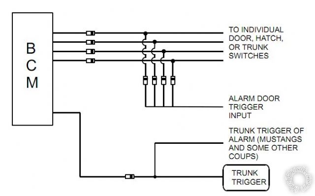
the issue is the bcm sends a negative pulse down the door trigger lines. you need to put a diode inline from the door trigger to the bcm. from there, another diode from the inline diode to your neg trigger if that makes sense. essentially, one diode inline will prevent the "pulse" from the bcm, the other allows 4 doors to be wired together. this is just diode isolating the 4 triggers
Ted
2nd Year Tier 1 Medical School
Still installing as a hobby...pays for groceries
Compustar Expert
jcran17 
Member - Posts: 12
Member spacespace
Joined: February 13, 2007
Posted: March 14, 2012 at 9:51 AM / IP Logged  
tedmond wrote:
the issue is the bcm sends a negative pulse down the door trigger lines. you need to put a diode inline from the door trigger to the bcm. from there, another diode from the inline diode to your neg trigger if that makes sense. essentially, one diode inline will prevent the "pulse" from the bcm, the other allows 4 doors to be wired together. this is just diode isolating the 4 triggers
Thanks Ted. And to confirm, the inline diodes will need to be installed with cathode end facing towards the door and the individual 4 diodes taping in on the door side of the inline diodes?
jcran17 
Member - Posts: 12
Member spacespace
Joined: February 13, 2007
Posted: March 14, 2012 at 11:33 AM / IP Logged  
Thanks Ted. Found a diagram of what you were saying. I will give it a try an let you know how it shakes out.
06 f150 w/5704 remote start sets of alarm - Page 2 -- posted image.
tedmond 
Gold - Posts: 4,610
Gold spaceThis member has been recognized as an authority in Mobile Security and Convenience. Click here for more info.spacespace
Joined: January 06, 2007
Location: Ontario, Canada
Posted: March 14, 2012 at 11:36 AM / IP Logged  
precisely that's the diagram you want to use. I was trying to copy the diagram from wiremagic, but you cant copy it.
Ted
2nd Year Tier 1 Medical School
Still installing as a hobby...pays for groceries
Compustar Expert
enice 
Silver - Posts: 857
Silver spacespace
Joined: March 05, 2006
Location: New York, United States
Posted: March 15, 2012 at 10:48 PM / IP Logged  
Just connect the positive wire to the dome light positive trigger to give you less issues. I can look up the car at my shop tomorrow in our mitchell guide to confirm the negative door trigger.
Page of 3

  Printable version Printable version Post ReplyPost New Topic
You cannot post new topics in this forum
You cannot reply to topics in this forum
You cannot delete your posts in this forum
You cannot edit your posts in this forum
You cannot create polls in this forum
You cannot vote in polls in this forum

  •  
Search the12volt.com
Follow the12volt.com Follow the12volt.com on Facebook
Friday, March 29, 2024 • Copyright © 1999-2024 the12volt.com, All Rights Reserved Privacy Policy & Use of Cookies
Disclaimer: *All information on this site ( the12volt.com ) is provided "as is" without any warranty of any kind, either expressed or implied, including but not limited to fitness for a particular use. Any user assumes the entire risk as to the accuracy and use of this information. Please verify all wire colors and diagrams before applying any information.

Secured by Sectigo
the12volt.com spacer
Support the12volt.com
Top
the12volt.com spacer