the12volt.com spacer
icon

led third brake light relay


Post ReplyPost New Topic
< Prev Topic Next Topic >
bbstacker 7072 
Member - Posts: 11
Member spacespace
Joined: March 02, 2012
Location: North Carolina, United States
Posted: March 02, 2012 at 8:30 PM / IP Logged  
Almost embarrassed to post this. I have a 2005 Scion xb(auto trans) with the Rostra 250-1755. It has worked fine for years until I installed an led third brake light. Rostra has a fix. Install a spdt relay to present ground to the cruise, as it can't see it through the led tbl.
led third brake light relay -- posted image.
The relay is energizing when I hit the brake and the tbl works. The problem arises when I connect the violet wire from the Rostra-immediately blows the stop light fuse. It appears I need someone to tell me how to connect the violet correctly. I have the chassis grounds under control and the relay coil is functioning. I just don't know why the fuse blows when connecting gd to gd. Thank you.
oldspark 
Gold - Posts: 4,913
Gold spacespace
Joined: November 03, 2008
Location: Australia
Posted: March 02, 2012 at 9:50 PM / IP Logged  
Not that I see any peculiarities with the Rostra, but please allow for the experienced gurus on this site to respond or confirm...
But why would a 3rd brake LED light be an issue - it should just be connected in parallel with the existing brake lights (whether +ve or GND switched).
If the existing brake lights are also LEDs, then any bulb-out alarm won't sense properly (until at least 2 of the 3 fail), but that shouldn't effect the cruise control.
As usual, it's always nice to see some authority using 86 to vehicle GND instead of 85.
[ Not that I care - I never use relays with internal (spike protection) diodes. But for those that do, it's a good way to "unprotect" the spike (with initial smoke) or blow the signal's fuse or circuit. (Maybe that's your problem? POST EDIT - no, it can't be...) ]
POST EDIT #2:
The diagram shows Violet being connected to GND, yet the installation instructions (250-1755_Form4838.pdf) under Appendix A. ELECTRICAL TESTING (A4 - Power Brake Circuit) states "IGNITION “ON” 12VDC ON VIOLET WIRE", and your diagram above states "do not let the violet wire see ground...", yet it is connecting violet to GND when the brake lights are on.
The latter suggests stop bulbs which are a low resistance to GND.
IMO #30 of the relay should be to (the brake circuit's) +12V - not to GND.
But why would LEDs be a issue if bulbs are not...?
Howie - where are you?
bbstacker 7072 
Member - Posts: 11
Member spacespace
Joined: March 02, 2012
Location: North Carolina, United States
Posted: March 02, 2012 at 10:17 PM / IP Logged  
Good eye, oldspark. I never saw the 12v indication for violet on the troubleshooting chart. I never had any problems when I installed it. Here, verbatim, is what the tech at Rostra sent me with the link to the relay fix: The use of LED taillights will cause our cruise control to stop working. For a workaround, please see the FAQ section on our website's "Support" page at the link below. You will find instructions on how to wire in an accessory relay to complete the circuitry from your brake switch that our cruise control needs to see before it will turn itself on.
Thanks for your help. I'm sure that airing all of this information will get me some interesting answers.
oldspark 
Gold - Posts: 4,913
Gold spacespace
Joined: November 03, 2008
Location: Australia
Posted: March 03, 2012 at 2:27 AM / IP Logged  
Keeping in mind that I usually stay away from these types of problems. Whilst I was of benefit with older system on local forums (downunder in OzTralia), these days I stand no chance against those hereon. I might be able to iterate forward IF I'm lucky, but these other gurus get straight to the solution and can include a good explanation.
But in this case, assuming brake bulbs, how the heck can adding a parallel LED array effect things? The added load is insignificant and electrically, the bulbs essentially short out the LEDs - ie, any rectification by the LEDs is bypassed via the bulbs. The resistance (& impedance) of the bulb/LED circuit will be indistinguishable from the bulbs alone (usually that is - ie, to within about 2%).
That's what attracted my reply. I wasn't even going to look at Rostra, but in case it was new confustigated thingamajiggy, I did. But it was a mere cruise control. (Yes - you mentioned "cruise", but to me that could have referred to audio or even a hair-blower.)
Then as I wrote my reply I got distracted into more & more detail. (Good! I reread your OP and diagram, and looked harder at the Rostra info. I often make the mistake of a quick read and total misunderstanding.)
And then I picked the two "
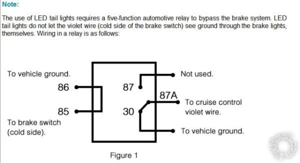
don't ground the violet" info bits which IMO contradicted the relay wiring. (Obviously? Yes?)
Not that I am comfortable wiring violet (#30) direct to whatever +12V - you'd better wait for some confirmation first (though it "feels" pretty safe - if ground blows a fuse, the it is unlikely that +12V will do damage, but it might).
[ BTW - I added so much to my original reply that I deleted and reposted the modified reply. (For the reason I described in my earlier l-o-n-g 2nd reply to strikethrough.) ]
And not that I know what the violet is, but if it's a brake sensing input, isn't it strange that EVERY user would have to add a relay? If the cold side of the switch is bulbs, then violet sees ground through a 4 Ohm resistance if it's two ~21W bulbs. If it's a LED array, the resistance is probably well above 200 Ohms (plus a voltage drop across the LEDs), so why would LEDs be a problem if bulbs aren't?
But that's where I'll play lazy and wait for others to explain. Howie will probably bedazzle me again with his awesome Unobtainium else Platinum knowledge and experience. Else someone else...
After all, it may not be a mere sensing circuit.
I was tempted to comment about companies that have +/- to a relay as 85/86 instead of the accepted norm of 86/85 and how that alone can make me suspicious. But if I'm right about the above - whether what LED impact?, else shouldn't #30 be to +12V? (and now, why the brake to get the unit to start operating?) - then I'd be real tempted to make a comment about stupid techs etc. I might then write what I've just written. But in case I'm wrong, I'll refrain. (ha bluddy ha!)
Oops, I digressed yet again... But funny how this reminds me of my recent "quality" and "un-controlled (document)" comments. Geez, I'm such an egotistical female canine.
howie ll 
Pot Metal - Posts: 16,466
Pot Metal spacespace
Joined: January 09, 2007
Location: United Kingdom
Posted: March 03, 2012 at 4:32 AM / IP Logged  
Howard belatedly goes with ignore the relay and the LED brake light, all you are looking for is 12v coming from the switched side of the brake light to disengage the cruise control.
If the third brake light effects other things and I can't see how may I suggest a 1N4004 in line band towards the LED.
oldspark 
Gold - Posts: 4,913
Gold spacespace
Joined: November 03, 2008
Location: Australia
Posted: March 03, 2012 at 4:59 AM / IP Logged  
Some people make me feel REAL good. (FIGJAM...)
Now, about certain professional technicians... (There's only one "o" in moron.)
I'd love to see a "please explain" (by the above tech)!
howie ll 
Pot Metal - Posts: 16,466
Pot Metal spacespace
Joined: January 09, 2007
Location: United Kingdom
Posted: March 03, 2012 at 5:15 AM / IP Logged  
Oh, justification required.
Is the cruise violet it's brake light shut down feed?
If so it needs to see a pos for every vehicle I can think of except Lincoln Town Car/S type Jag, 98 on.
The way that relay is set up, bang.
My thought is that LEDs retain some capacitance so therefore I'd use the diode as a simple "anti-feedback"
I just tried some 12volt LEDs equivalent to 10watt wedge bulbs and dumped the power from my 35amp stabilised power supply,
bloody 13 seconds on full power till fade!
I think that's the reason.
oldspark 
Gold - Posts: 4,913
Gold spacespace
Joined: November 03, 2008
Location: Australia
Posted: March 03, 2012 at 6:51 AM / IP Logged  
But that's the PSU's output capacitor (not the LED's).
But the effect is the same - LEDs may cause Rostra input filter capacitance to decay too slowly.
But the that's only relevant if bulbs are replaced by LEDs - the bulbs will discharge any such capacitance quickly (at least 100-200 times faster than LEDs). Hence if LEDs are paralleled with bulbs, it should be a negligible effect.   
No matter what, parallel bulbs should swamp the effect of LEDs. When unpowered, the bulbs are essentially a short circuit across the LED - eg, 8, 4 or 2 Ohms etc across (say) an 80 to 500 Ohm resistor (in series with a Zenor = equivalent LED series voltage).
And even then, if it is the "brake sensor" that disconnects the cruise control as soon as the brake is pressed (ie, +12V appears), then so what about the decay. (Unless the cruise can be re-enabled whist the brake is still applied, but surely no design is that stupid?)
Damn it - shall we inspect the full wiring or Rostra system?
I might be interested, but only after:
- it is determined that "normal and proper" connection to standard brake lights causes failure (or non-initiation);
- that addition of a LED across the stop lamp(s) causes failure...
- and that the addition of the relay has NOT been solely due to some advice, but in response to reality.
If only LEDs (no bulbs) is the only issue, I'd be curious why if the above are okay, but I'd put that down to an (IMO) crap design. But that assumes violet is the brake sensing to disengage the cruise.
[ I know the system gave problems with the addition of the 3rd (LED) brake light, but was that LED wired correctly OR does a 3rd bulb do the same. IE - the 3rd is not wired opposite to +12V switched brake lights (as if to be GND switched)? ]
[Caveat: It is late...]
An astute person recently wrote:
... I'm sure that airing all of this information will get me some interesting answers.
Don't you hate when noobs are so right?
And they think they are embarrassed? Ha!
howie ll 
Pot Metal - Posts: 16,466
Pot Metal spacespace
Joined: January 09, 2007
Location: United Kingdom
Posted: March 03, 2012 at 8:04 AM / IP Logged  
OP, please don't ever be embarrassed to ask a question.
The point our friend makes is to test.
Does the problem go if you take
1) The relay, or
2) The LED lamp out of the equation.
bbstacker 7072 
Member - Posts: 11
Member spacespace
Joined: March 02, 2012
Location: North Carolina, United States
Posted: March 03, 2012 at 9:43 AM / IP Logged  
Thanks, howie II, I appreciate that. To answer your query, yes to both. The original filament bulb is 2 ohms. Could I just put a 2 ohm resistor of sufficient wattage in parallel with the led to simulate the signal needed by the cruise control. The part that gets me is that my right and left brake lights are led as well and that posed no issue until I replaced the third brake light with an led. If you go to this pdf and go to page 13 within the pdf, you'll see the stop light diagram for my car on the far right. led third brake light relay -- posted image.
Actually, I'm not using the relay and it is back as it was: led brake works, but cruise control doesn't. The instant I turn on the cruise control the abs/trac/vsc lights illuminate on the dash.
Think ya' used enough dynamite there, Butch?
Page of 5

  Printable version Printable version Post ReplyPost New Topic
You cannot post new topics in this forum
You cannot reply to topics in this forum
You cannot delete your posts in this forum
You cannot edit your posts in this forum
You cannot create polls in this forum
You cannot vote in polls in this forum

  •  
Search the12volt.com
Follow the12volt.com Follow the12volt.com on Facebook
Thursday, March 28, 2024 • Copyright © 1999-2024 the12volt.com, All Rights Reserved Privacy Policy & Use of Cookies
Disclaimer: *All information on this site ( the12volt.com ) is provided "as is" without any warranty of any kind, either expressed or implied, including but not limited to fitness for a particular use. Any user assumes the entire risk as to the accuracy and use of this information. Please verify all wire colors and diagrams before applying any information.

Secured by Sectigo
the12volt.com spacer
Support the12volt.com
Top
the12volt.com spacer