


Posted: July 19, 2012 at 3:26 AM / IP Logged
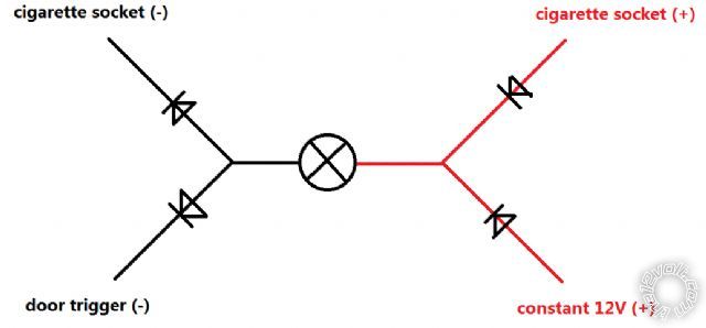 Hi everyone, I have some problem in the circuit using this relay. So basically, it is some LED lights that I want them on when the door is open, also can be turned on/off with a switch that connected to the 12v cigarette socket. So as shown in the figure above, the top half is the socket line, while the bottom half is the door trigger line.
I used diodes to isolate the two lines, as shown in the figure.
However, I figured out that in the cigarette socket line, the +12v is controlled by the ignition, while the (-) is always connected to chassis ground. While in the door trigger line, the +12V is constant, and the (-) is provided only when any door is opened. So the situation becomes the second figure:
Hi everyone, I have some problem in the circuit using this relay. So basically, it is some LED lights that I want them on when the door is open, also can be turned on/off with a switch that connected to the 12v cigarette socket. So as shown in the figure above, the top half is the socket line, while the bottom half is the door trigger line.
I used diodes to isolate the two lines, as shown in the figure.
However, I figured out that in the cigarette socket line, the +12v is controlled by the ignition, while the (-) is always connected to chassis ground. While in the door trigger line, the +12V is constant, and the (-) is provided only when any door is opened. So the situation becomes the second figure:
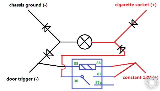 As you can see, since one line has constant +12v, while the other has constant ground, the LED is always on. So I designed to add a relay in it, as shown above. So when the door trigger (-) is not present, the relay cuts the constant +12v, so problem solved.
However, I found that every time when the door is shut, that is to say when the relay input is cut, the relay makes a noise. Is that called spike I guess? I tried to switch the 85 and 86, now which 85-ground 86-12V, but the spike is still there. Why?
And BTW, if there is no way to kill the spike noise in the current design, could anyone come up with a better solution?
Many thanks!! Really want to get rid of the noise ASAP.
As you can see, since one line has constant +12v, while the other has constant ground, the LED is always on. So I designed to add a relay in it, as shown above. So when the door trigger (-) is not present, the relay cuts the constant +12v, so problem solved.
However, I found that every time when the door is shut, that is to say when the relay input is cut, the relay makes a noise. Is that called spike I guess? I tried to switch the 85 and 86, now which 85-ground 86-12V, but the spike is still there. Why?
And BTW, if there is no way to kill the spike noise in the current design, could anyone come up with a better solution?
Many thanks!! Really want to get rid of the noise ASAP.
Posted: July 19, 2012 at 3:28 AM / IP Logged

Posted: July 19, 2012 at 6:34 AM / IP Logged
Posted: July 19, 2012 at 3:14 PM / IP Logged
Posted: July 19, 2012 at 4:20 PM / IP Logged
Posted: July 19, 2012 at 4:26 PM / IP Logged
Posted: July 19, 2012 at 4:28 PM / IP Logged
Posted: July 19, 2012 at 7:20 PM / IP Logged
Posted: July 19, 2012 at 7:23 PM / IP Logged
Posted: July 19, 2012 at 7:31 PM / IP Logged
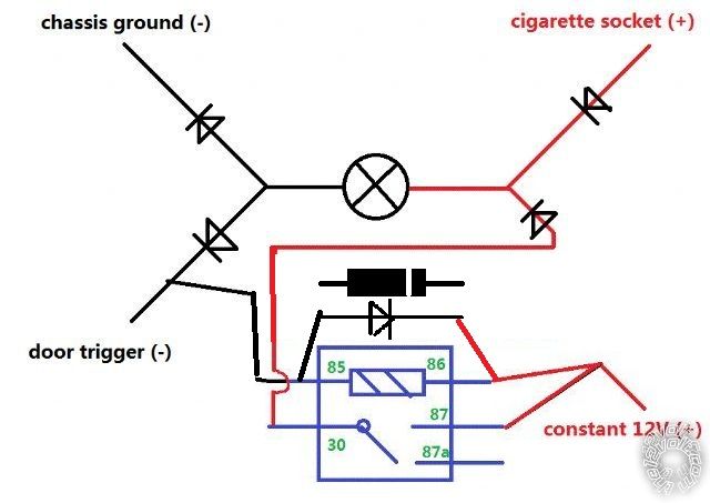 just want to make sure, after crossing a diode on the coil, it looks like this.
double checked that diode is 1N4004, used one to cross. (may be try multiple?)
just want to make sure, after crossing a diode on the coil, it looks like this.
double checked that diode is 1N4004, used one to cross. (may be try multiple?) Printable version
| You cannot post new topics in this forum You cannot reply to topics in this forum You cannot delete your posts in this forum You cannot edit your posts in this forum You cannot create polls in this forum You cannot vote in polls in this forum |

| Search the12volt.com |
Follow the12volt.com 
Friday, May 8, 2026 • Copyright © 1999-2026 the12volt.com, All Rights Reserved • Privacy Policy & Use of Cookies

Friday, May 8, 2026 • Copyright © 1999-2026 the12volt.com, All Rights Reserved • Privacy Policy & Use of Cookies
Disclaimer:
*All information on this site ( the12volt.com ) is provided "as is" without any warranty of any kind, either expressed or implied, including but not limited to fitness for a particular use. Any user assumes the entire risk as to the accuracy and use of this information. Please
verify all wire colors and diagrams before applying any information.
