the12volt.com spacer
icon

02 Pontiac Grand Prix, Viper 5704


Post ReplyPost New Topic
< Prev Topic Next Topic >
kreg357 
Platinum - Posts: 7,783
Platinum spaceThis member has made a donation to the12volt.com. Click here for more info.spaceThis member has been recognized as an authority in Electrical Theory. Click here for more info.spaceThis member has been recognized as an authority in Mobile Security and Convenience. Click here for more info.spacespace
Joined: January 30, 2009
Location: Pennsylvania, United States
Posted: July 29, 2012 at 10:58 AM / IP Logged  

Looks like only two diodes for the door triggers on the 4 door sedan, as per this note from DEI :

The tan is located in the drivers kick and catches only the drivers door. The dark/blue is located in the passenger kick panel and

catches all other doors, must diode isolate these wires.

Soldering is fun!
alexp1289 
Copper - Posts: 96
Copper spacespace
Joined: July 28, 2012
Location: New Hampshire, United States
Posted: August 01, 2012 at 3:23 PM / IP Logged  
ok so i am trying to flash the 1.00 firmware and Optimax Flash doesnt see my bypass module 0_0 wth????? Any help would be great :) It does say usb device found but thats all it says :(
kreg357 
Platinum - Posts: 7,783
Platinum spaceThis member has made a donation to the12volt.com. Click here for more info.spaceThis member has been recognized as an authority in Electrical Theory. Click here for more info.spaceThis member has been recognized as an authority in Mobile Security and Convenience. Click here for more info.spacespace
Joined: January 30, 2009
Location: Pennsylvania, United States
Posted: August 01, 2012 at 5:59 PM / IP Logged  

Not sure where you are at on this.  The Optimax section is only for bypass modules that DEI OEM's from Fortin, like the PKALL

and DLPK.  The XK0x series are standard DEI modules.  With the XKLoader plugged in, try going to this URL : http://www.xpresskit.com/
At that point, select your vehicle from the pull down menus.

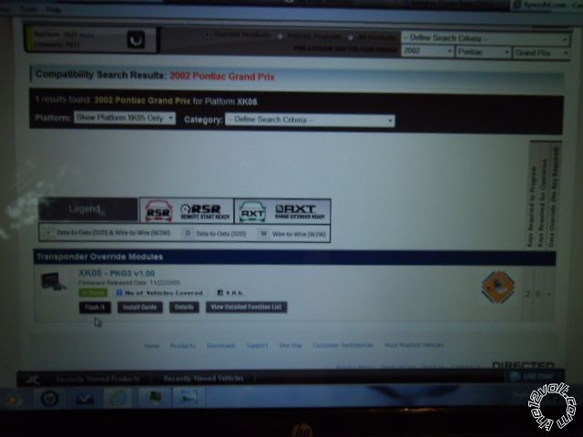
That should give you this screen :

02 Pontiac Grand Prix, Viper 5704 - Page 3 -- posted image.

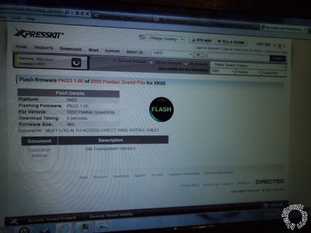
Notice that the box in the upper left area ID's your bypass module.  Click on "Flash It" in the lower left area.  That should give you this screen :

02 Pontiac Grand Prix, Viper 5704 - Page 3 -- posted image.

You will need to have previously downloaded some S/W and drivers from DEI to get these screens.

Soldering is fun!
alexp1289 
Copper - Posts: 96
Copper spacespace
Joined: July 28, 2012
Location: New Hampshire, United States
Posted: August 21, 2012 at 6:08 PM / IP Logged  
Ok guys i need a little help and guidance here. Im making my wiring refrance diagram for the viper remote starter connections. Here is a refrence sheet for my car--- https://www.dropbox.com/s/cg8ui2kx19sahsj/2002%20Grand%20Prix%20Wire%20Diagram.doc
And here is what i have so far for the remote start wires.
REMOTE START 10-PIN HEAVY GUAGE CONNECTOR
Fused Connections-
Red (Ignition Input- 1)
RED / White (Ignition- 2 Flex Relay Input)
RED / Black (Starter Input/Accessory)
Regular Connections-
Pink (Ignition Input/Output- 1)
Orange (Accessory Output)
Green (Starter Input- “Key Side Kill”)
Violet (Starter Output- “Car Side Kill”)
Pink/White (Ignition- 2 Flex Relay Output)
Pink/Black (Flex Relay Input “Key Side If Required”)
The other thing im not sure of is if some of these need to be just need to be tapped into and which ones need to be cut. So that one side can be input from the key side and the other is hooked up to output for car side. Im learning slowly :/
Please help me figure out which wires go where and feel free to edit and add to what i have. Im hoping to have a complete document i can look at while installing. But i need your help :)
howie ll 
Pot Metal - Posts: 16,466
Pot Metal spacespace
Joined: January 09, 2007
Location: United Kingdom
Posted: August 21, 2012 at 6:25 PM / IP Logged  
Cut the starter wire, key side to green and starter motor side to violet.
All others are soldered, remember pink to ignition 1 and pink/white to ignition 2.
Also 3 ACC wires, orange to ACC 1.
Satellite loom orange low NEG 2nd. ACC output via 2 1N4004 diodes in a "Y" shape to a pair of relays, orange to both 85, 30amps fused to 86 and 87 each relay, then 30 on each relay to ACC 2 and ACC 3.
Absolutely mandatory or you WILL throw a DTC.
When you say "patch" how are you joining the cables?
Over to Kregg, it's 12:30am and I'm off to sleep.
howie ll 
Pot Metal - Posts: 16,466
Pot Metal spacespace
Joined: January 09, 2007
Location: United Kingdom
Posted: August 21, 2012 at 6:28 PM / IP Logged  
Cut the starter wire, key side to green and starter motor side to violet.
All others are soldered, remember pink to ignition 1 and pink/white to ignition 2.
Also 3 ACC wires, orange to ACC 1.
Satellite loom orange low NEG 2nd. ACC output (H2/22) via 2 1N4004 diodes in a "Y" shape to a pair of relays, orange to both 85, 30amps fused to 86 and 87 each relay, then 30 on each relay to ACC 2 and ACC 3.
Absolutely mandatory or you WILL throw a DTC.
When you say "patch" how are you joining the cables?
Over to Kregg, it's 12:30am and I'm off to sleep.
alexp1289 
Copper - Posts: 96
Copper spacespace
Joined: July 28, 2012
Location: New Hampshire, United States
Posted: August 21, 2012 at 6:41 PM / IP Logged  
I'm soldering all my connections. When you ask about me patching wires I meant tapping into them because I have a tool that allows me to strip the wire without cutting. The others I have to cut so I have a key side input and a car side output.
Also I have a question about the flex relay wires. Are they needed on my car or not? And if so where do they go and yo what colors? I'm slowly gaining the confidence for the install but I'm doing a lot of asking questions and planning as you can see.
kreg357 
Platinum - Posts: 7,783
Platinum spaceThis member has made a donation to the12volt.com. Click here for more info.spaceThis member has been recognized as an authority in Electrical Theory. Click here for more info.spaceThis member has been recognized as an authority in Mobile Security and Convenience. Click here for more info.spacespace
Joined: January 30, 2009
Location: Pennsylvania, United States
Posted: August 21, 2012 at 7:46 PM / IP Logged  

Use a DMM and verify all wires at ignition switch harness.

Constant 12V+ Wire: Red ( and possibly RED / White )         Split load between H3/2, H3/6

Constant 12V+ Wire Location: Ignition Switch Harness     and H3/9 ( and H1/2 )

Starter Wire (+): Yellow             Cut wire  H3/4 car side

Starter Wire Location: Ignition Switch Harness             H3/5 key side

Second Starter Wire (+): N/A

Second Start Wire Location: N/A

Ignition Wire (+): Pink                 H3/1

Ignition Wire Location: Ignition Switch Harness

Second Ignition Wire: White                   H3/7  Program default = IGN2

Second Ignition Wire Location: Ignition Switch Harness     

Accessory Wire: Orange                          H3/3

Accessory Wire Location: Ignition Switch Harness

Second Accessory Wire: Brown       External Relay controlled by

Second Accessory Wire Location: Ignition Switch Harness    ORANGE (-) 200mA ACCESSORY OUTPUT
                  This Brown ACC2 wire might not be 
      necessary for remote start.

H3/1 PINK (+) IGNITION 1 INPUT/OUTPUT Pink

H3/2 RED / WHITE (+) FUSED (30A) IGNITION 2 / FLEX RELAY INPUT 87 Red
H3/3 ORANGE (+) ACCESSORY OUTPUT   Orange
H3/4 VIOLET (+) STARTER OUTPUT (CAR SIDE OF THE STARTER KILL)           Yellow
H3/5 GREEN (+) STARTER INPUT (KEY SIDE OF THE STARTER KILL WIRE)    Yellow
H3/6 RED (+) FUSED (30A) IGNITION 1 INPUT        Red
H3/7 PINK/WHITE (+) IGNITION 2 / FLEX RELAY OUTPUT              White
H3/8 PINK/BLACK (+) FLEX RELAY INPUT 87A key side of FLEX RELAY               N.U.
H3/9 RED / BLACK (+) FUSED (30A) ACCESSORY/STARTER INPUT          Red
H3/10 NC (no connection)  NC

ACC2 external relay ( 30/40 Amp SPDT ) if needed  :

Relay Pin 85 to ORANGE (-) 200mA ACCESSORY OUTPUT
Relay Pin 86 and 87 to +12V constant fused at 20 Amps
Relay Pin 30 to Brown ACC2 wire
Relay Pin 87A not used - insulate

Soldering is fun!
howie ll 
Pot Metal - Posts: 16,466
Pot Metal spacespace
Joined: January 09, 2007
Location: United Kingdom
Posted: August 22, 2012 at 2:53 AM / IP Logged  
Now you've had the satellite relay question answered 3 times, once by me before you even posted!
Sorry, I somehow read it as 3 ACC wires not two, scratch the post regarding 2 relays, only one required.
AFIK not connecting BOTH ACC wires will throw trouble codes/transmission problems (DTC s).
alexp1289 
Copper - Posts: 96
Copper spacespace
Joined: July 28, 2012
Location: New Hampshire, United States
Posted: August 22, 2012 at 9:54 AM / IP Logged  
What do you guys mean when you say to split the load of the 12v constant wire? Also the reference sheet you posted is a little confusing. Is the left side the wires coming from the viper? And the right side the color of the car wires? Also what do you mean about the satellite relay?
Page of 17

  Printable version Printable version Post ReplyPost New Topic
You cannot post new topics in this forum
You cannot reply to topics in this forum
You cannot delete your posts in this forum
You cannot edit your posts in this forum
You cannot create polls in this forum
You cannot vote in polls in this forum

  •  
Search the12volt.com
Follow the12volt.com Follow the12volt.com on Facebook
Thursday, April 25, 2024 • Copyright © 1999-2024 the12volt.com, All Rights Reserved Privacy Policy & Use of Cookies
Disclaimer: *All information on this site ( the12volt.com ) is provided "as is" without any warranty of any kind, either expressed or implied, including but not limited to fitness for a particular use. Any user assumes the entire risk as to the accuracy and use of this information. Please verify all wire colors and diagrams before applying any information.

Secured by Sectigo
the12volt.com spacer
Support the12volt.com
Top
the12volt.com spacer