the12volt.com spacer
icon

delay off relay


Post ReplyPost New Topic
< Prev Topic Next Topic >
jmv5171195 
Member - Posts: 18
Member spacespace
Joined: February 19, 2012
Location: Pennsylvania, United States
Posted: August 17, 2012 at 7:46 PM / IP Logged  
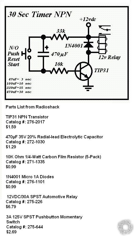
Saw this diagram on here in another thread and was wondering if I could replace the Capacitor in this diagram with a Potentiometer to give me the abilities to change the delay by just using the switch.Is this possible?
delay off relay -- posted image.
oldspark 
Gold - Posts: 4,913
Gold spacespace
Joined: November 03, 2008
Location: Australia
Posted: August 18, 2012 at 12:29 AM / IP Logged  
No, you replace the resistor with a pot.
jmv5171195 
Member - Posts: 18
Member spacespace
Joined: February 19, 2012
Location: Pennsylvania, United States
Posted: August 18, 2012 at 8:47 AM / IP Logged  
Which resistor would I replace the 10K or the 33K? Could I make this without the push button switch. Also how does the relay wire up as in where does my output to the light go?
Thank you for the help so far!
oldspark 
Gold - Posts: 4,913
Gold spacespace
Joined: November 03, 2008
Location: Australia
Posted: August 18, 2012 at 10:10 AM / IP Logged  
The 33k.
But that may not be the the circuit you want.
It's a "pulse" timer.
When first powered up, it turns the relay on for the delay time (ie, ~30 seconds as determined by the 33k & cap).   
Thereafter, pressing the switch turns it on again and it turns off !30 seconds after opening (letting go) of the switch.
The relay contacts (top RHS of the diagram) would control your light.
jmv5171195 
Member - Posts: 18
Member spacespace
Joined: February 19, 2012
Location: Pennsylvania, United States
Posted: August 18, 2012 at 10:35 AM / IP Logged  
Ah I see. I don't think this is going to work then. What I'm looking for is a circuit that powers up for a set time by a negative trigger. The application is for my remote start that isn't equipped with illuminated entry. When the remote start receives a signal to lock or unlock, the circuit is activated and lights the dome light up for the specified time period.
oldspark 
Gold - Posts: 4,913
Gold spacespace
Joined: November 03, 2008
Location: Australia
Posted: August 18, 2012 at 11:11 AM / IP Logged  
Have a look at the 555 timer in monostable mode. Pin #2 is a -ve trigger input (as I recall).
The 555 consumes 10mA in standby mode, though the CMOS equivalent (the 7555?) should consume far less.
There is also the possibility of using a PICAXE 08 - an 8 pin chip, plus a 5V regulator, 2 programming resistors and an output buffer (eg, 2 resistors & a transistor, or a MOSFET to drive a relay or whatever) plus whatever input is required.
Though that has the programming overhead (ie, a PC serial port), the advantage is its fully programmable possibilities using up to ~5 inputs and up to ~5 output.
jmv5171195 
Member - Posts: 18
Member spacespace
Joined: February 19, 2012
Location: Pennsylvania, United States
Posted: August 18, 2012 at 1:13 PM / IP Logged  
The PICAXE 08 sounds real cool but a little overkill for just a dome light. Would the monostable mode of this chip work?
Once again thank you very much for the help, my knowledge of micro controllers are little. delay off relay -- posted image.
oldspark 
Gold - Posts: 4,913
Gold spacespace
Joined: November 03, 2008
Location: Australia
Posted: August 18, 2012 at 7:47 PM / IP Logged  
Yes, that's the 555 albeit the CMOS version (lower power draw).
You should find lots of circuits on the web to confirm your design.
The delay time is something like R x C.
It may only output 200mA so a transistor etc may be needed.
Beware of CMOS handling if using the 7555 (no static electricity).
It should handle normal vehicle voltages but protection may be worthwhile.
Usually the +V (+12V) is via a diode (IN4004etc) for polarity protection, and a low-value resistor followed by a Zenor diode (say ~15V)to pin 8 (& 4).
The output load (eg relay) can be driven from the raw +12V if a ground switched output transistor (or MOSFET) is used. Hence the +12V series resistor only has to carry the 555 operating current (ie, 10-20mA; less for 7555) without too high a voltage drop. (Driving the 200mA output means a 10x to 20x smaller resistor with a higher wattage rating, and a Zenor rating to suit.)
Protect the input as well. Usually thru a resistor and "reverse connected" diodes to both +V & 0V (GND).
And usually a pull-up resistor (if pin 2) to keep un-triggered until the -ve pulse.   
jmv5171195 
Member - Posts: 18
Member spacespace
Joined: February 19, 2012
Location: Pennsylvania, United States
Posted: August 18, 2012 at 8:39 PM / IP Logged  
I could live with having the output load run 200mA and just have it drive a relay.My 12v input is going to pin 8 and 4 correct?The more I reread your instructions the more I start to pick up.Thanks yet again!
oldspark 
Gold - Posts: 4,913
Gold spacespace
Joined: November 03, 2008
Location: Australia
Posted: August 19, 2012 at 5:10 AM / IP Logged  
Yep. Follow the 555 info. Pin #1 is GND, pin #8 is +V but #4 (Reset) is usually tied to +V (#8) to avoid false resets.
See technologystudent-elec1-5554.htm to confirm your circuit.
Your relay would be connected in place of the buzzer of the 555 drives the relay direct (but omit the buzzer's diode to +V and place it across the relay coil as shown in the 2nd relay diagram).
Else use the relay driver circuit output if using a transistor as per the 2nd diagram. Note that then the relay coil is connected from +V (#86) with it's -ve end (#85) to the transistor output (its Collector).
The "Relay Toggle Circuit Using a 556 Timer" down the page at bowdenshobbycircuits-page9 may be better for its transistor details, though I think I prefer the previous links wiring for pin #2 etc.
Another good 555 reference is kpsec.freeuk-555timer.
Page of 4

  Printable version Printable version Post ReplyPost New Topic
You cannot post new topics in this forum
You cannot reply to topics in this forum
You cannot delete your posts in this forum
You cannot edit your posts in this forum
You cannot create polls in this forum
You cannot vote in polls in this forum

  •  
Search the12volt.com
Follow the12volt.com Follow the12volt.com on Facebook
Thursday, April 25, 2024 • Copyright © 1999-2024 the12volt.com, All Rights Reserved Privacy Policy & Use of Cookies
Disclaimer: *All information on this site ( the12volt.com ) is provided "as is" without any warranty of any kind, either expressed or implied, including but not limited to fitness for a particular use. Any user assumes the entire risk as to the accuracy and use of this information. Please verify all wire colors and diagrams before applying any information.

Secured by Sectigo
the12volt.com spacer
Support the12volt.com
Top
the12volt.com spacer