the12volt.com spacer
icon

car alarm wires


Post ReplyPost New Topic
< Prev Topic Next Topic >
kazaroza90 
Member - Posts: 7
Member spacespace
Joined: August 18, 2012
Location: Oregon, United States
Posted: August 21, 2012 at 7:27 PM / IP Logged  
Thank you very much my friend !!! I really wish to shake your hand for you help, and others help. Everything is working right now !!!
Yes you was right ;-) I did everything yesterday allmost at night, when got back home from work, so I screwed up the last connection. The lock wire , just simple 2 wires for arm disarm.
And another one from output harness's for arm/ disarm was good. So that's why when I got connected it chirped. )))
fuh...finally it's working...Next step:
a) starter killer ( I even have a diagram how it should be) ;
b) remote start control ;
c) power window ;
d) sunroof ;
e) trunk solenoid ;
Mr.Howie please check is I connected it okay. Like it suppose to be.
Thanks one more time http://farm9.staticflickr.com/8308/7834783740_19c8bd0c1c_b.jpg
The degree of your luck depends on your willingness to act
kazaroza90 
Member - Posts: 7
Member spacespace
Joined: August 18, 2012
Location: Oregon, United States
Posted: August 21, 2012 at 7:28 PM / IP Logged  
Why the picture doesn't work...
One more time car alarm wires - Page 2 -- posted image.
The degree of your luck depends on your willingness to act
kazaroza90 
Member - Posts: 7
Member spacespace
Joined: August 18, 2012
Location: Oregon, United States
Posted: August 21, 2012 at 8:46 PM / IP Logged  
It's very sad that I can't edit the message.
So the question what's nominal value of that's additional 2 diodes.
Also I googled and just found here that this one would be much easier.
Is it going to work ?car alarm wires - Page 2 -- posted image.
The degree of your luck depends on your willingness to act
howie ll 
Pot Metal - Posts: 16,466
Pot Metal spacespace
Joined: January 09, 2007
Location: United Kingdom
Posted: August 22, 2012 at 3:03 AM / IP Logged  
According to that nice photo you have the red going to 85 and the orange going to 86.
Turn them round, the diode band should face the POS side of the coil, you're OK if you haven't yet connected it, other wise you will have blown the diode and if wired up or left out there's a very good chance it will fry your R/S!
The relay diagram you posted*, plus the one I posted are effectively the SAME layout, I just showed the ORANGE (GWA) spurring out in a "Y" formation to feed window closers, therefore ALL those diodes (1N4004) are mandatory for protection.
*I've never even looked for or seen this diagram, I don't need to car alarm wires - Page 2 -- posted image.
It simply means that the original author and myself both did the right thing.
kazaroza90 
Member - Posts: 7
Member spacespace
Joined: August 18, 2012
Location: Oregon, United States
Posted: August 22, 2012 at 8:14 PM / IP Logged  
Yes, I got you. But I connected this wires according to the wires that comes from relay. And as you see that what I have on my relay
30 - white
87a - black
85 - red
86 - orange
And everything according this initial diagram, and wires that come from relay's pigtail.
And yes, I didn't fried my system because, first I wish to connect it on paper then in real life.
But anyway here is a picture that you clear see which one wire come from which pin (it's smooth but I marked them as you see)
car alarm wires - Page 2 -- posted image.
And I should connect like this ?
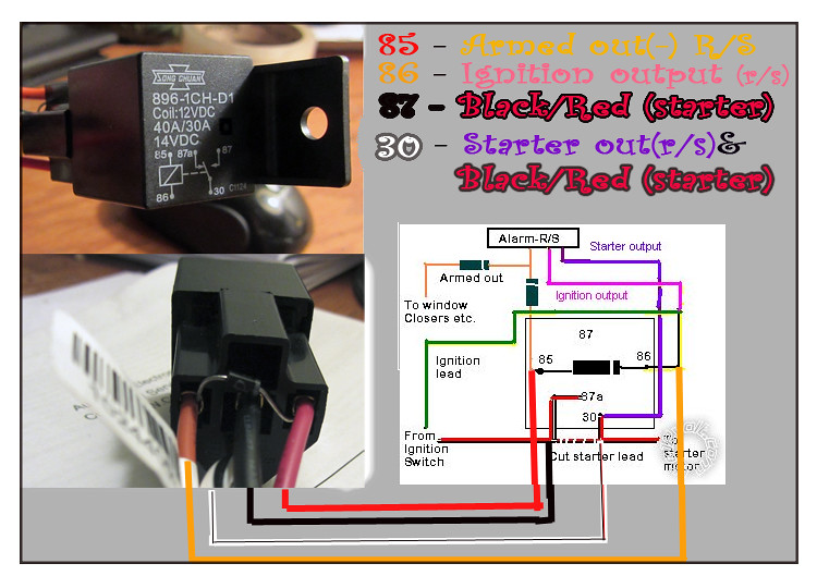
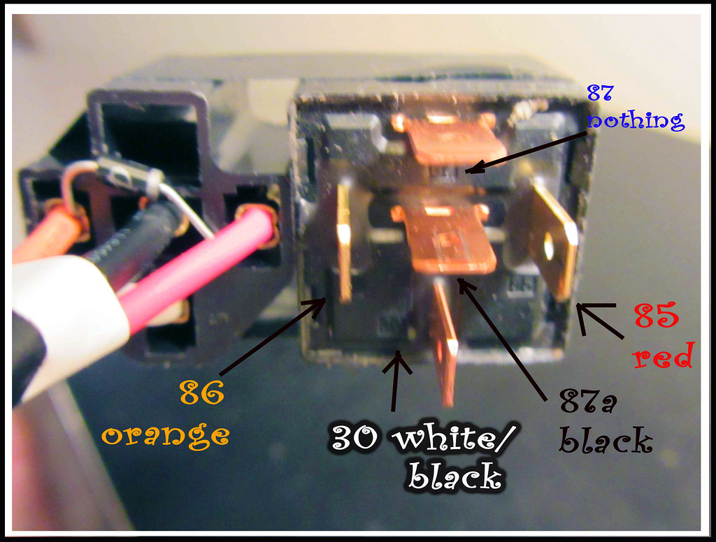
85red - to armed out(r/s)
86orange - to ignition green and pink (r/s)
87a black - to first part of cut starter's wire
30 white - to second part of cut starter's wire
So you should I swap like this :
1) 85red going to ignition green ;
2) 86 orange going to armed out ;
I'm totally frustrated because I did like the wire diagram said.
Hope that it's just mess in color from relay pigtail. Please clarify the situation for me. Thank you
The degree of your luck depends on your willingness to act
howie ll 
Pot Metal - Posts: 16,466
Pot Metal spacespace
Joined: January 09, 2007
Location: United Kingdom
Posted: August 23, 2012 at 2:00 AM / IP Logged  
You've done absolutely nothing wrong, it's just that by international convention, the same convention that makes the parking brake icon on your instrument panel the same whether your car is a Buick, BMW or Bentley (ISO) 85 is the NEG and 86 the POS.
Under MOST circumstances these two can be turned around.
It's just that in certain cases these relays already incorporate the diode internally and that would obviously cause problems.
Leave it as it is but make sure the red at 85 goes to ignition and the orange to your armed out.
It says a lot for a manufacturer that
a) They don't follow the convention.
b)Chinese relay rather than Bosch/Tycho etc.
Your photos are superb please PM me with how you did it!
Page of 2

Sorry, you can NOT post a reply.
This topic is closed.

  Printable version Printable version Post ReplyPost New Topic
You cannot post new topics in this forum
You cannot reply to topics in this forum
You cannot delete your posts in this forum
You cannot edit your posts in this forum
You cannot create polls in this forum
You cannot vote in polls in this forum

  •  
Search the12volt.com
Follow the12volt.com Follow the12volt.com on Facebook
Thursday, May 9, 2024 • Copyright © 1999-2024 the12volt.com, All Rights Reserved Privacy Policy & Use of Cookies
Disclaimer: *All information on this site ( the12volt.com ) is provided "as is" without any warranty of any kind, either expressed or implied, including but not limited to fitness for a particular use. Any user assumes the entire risk as to the accuracy and use of this information. Please verify all wire colors and diagrams before applying any information.

Secured by Sectigo
the12volt.com spacer
Support the12volt.com
Top
the12volt.com spacer