


time delay relay for horns


Posted: October 22, 2012 at 11:41 PM / IP Logged
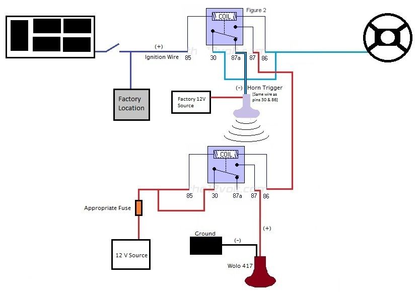 Ignition on, Wolo horn activated (factory horn deactivated):
 The horn trigger wire will be easiest to access from right near the factory horn, so I will probably do that. The only wire that I really need to find is the ignition wire. Tough finding a solid diagram or layout of the actual locations of the wires. Your descriptions are certainly helpful, though, just need to locate the bundle of wires.


Posted: October 23, 2012 at 6:17 AM / IP Logged
 Also, the ignition wire should be easy enough to find once you pull the lower panel off. It's the blue wire and will show 12v (or close to it) in the "On" and "Start" position.
Good Luck! Let me know how it turns out.
Also, the ignition wire should be easy enough to find once you pull the lower panel off. It's the blue wire and will show 12v (or close to it) in the "On" and "Start" position.
Good Luck! Let me know how it turns out.Posted: October 28, 2012 at 1:37 PM / IP Logged
Posted: October 28, 2012 at 3:19 PM / IP Logged
Sorry, you can NOT post a reply.
This topic is closed.
 Printable version
| You cannot post new topics in this forum You cannot reply to topics in this forum You cannot delete your posts in this forum You cannot edit your posts in this forum You cannot create polls in this forum You cannot vote in polls in this forum |

| Search the12volt.com |
Follow the12volt.com 
Wednesday, March 18, 2026 • Copyright © 1999-2026 the12volt.com, All Rights Reserved • Privacy Policy & Use of Cookies

Wednesday, March 18, 2026 • Copyright © 1999-2026 the12volt.com, All Rights Reserved • Privacy Policy & Use of Cookies
Disclaimer:
*All information on this site ( the12volt.com ) is provided "as is" without any warranty of any kind, either expressed or implied, including but not limited to fitness for a particular use. Any user assumes the entire risk as to the accuracy and use of this information. Please
verify all wire colors and diagrams before applying any information.
