the12volt.com spacer
icon

2006 saturn ion remote start


Post ReplyPost New Topic
< Prev Topic Next Topic >
keng1135 
Member - Posts: 7
Member spacespace
Joined: December 22, 2012
Location: Florida, United States
Posted: December 28, 2012 at 8:06 PM / IP Logged  
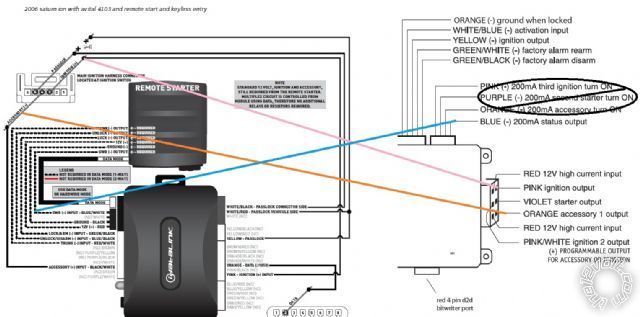
Hi im trying to install a remote start with keyless entry on my wife car. I know how to read a wiring diagram and got every wire figured out already. The one thing im confused is the ignition set of wires to my bypass. Im going to be installing a avital 4103 with idatalink bypass. Now does the remote start wiring gets tied into the bypass and then gets hooked into the ignition. I know the vehicle has tip start so the computer takes over for the starting so the starter output wire is not installed. Now there is a programmable output for accessory to ignition, not sure if that gets hooked up or not. I also got a diagram of the ignition with the two model please tell me if that is correct to tie into both model into the ignition the way i have it. Thanks for anyone who reply 2006 saturn ion remote start -- posted image.
keng1135 
Member - Posts: 7
Member spacespace
Joined: December 22, 2012
Location: Florida, United States
Posted: December 28, 2012 at 8:13 PM / IP Logged  
kreg357 
Platinum - Posts: 7,783
Platinum spaceThis member has made a donation to the12volt.com. Click here for more info.spaceThis member has been recognized as an authority in Electrical Theory. Click here for more info.spaceThis member has been recognized as an authority in Mobile Security and Convenience. Click here for more info.spacespace
Joined: January 30, 2009
Location: Pennsylvania, United States
Posted: December 29, 2012 at 7:55 AM / IP Logged  

First, ensure the iDatalink bypass module is flashed with the correct firmware for your vehicle.  You didn't mention which

iDatalink bypass module you are using but it appears to be GM4 firmware.  Also, you should connect the bypass module
to the Avital in the W2W mode.  That will be hardwiring all the dashed lines between the two modules.

Below is a note from the iDatalink install guide :

NOTE
STANDARD 12 VOLT, IGNITION AND ACCESSORY,
STILL REQUIRED FROM THE REMOTE STARTER.
MULTIPLEX CIRCUIT IS CONTROLLED FROM
MODULE USING DATA, THEREFORE NO ADDITIONAL
RELAYS OR RESISTORS REQUIRED.

In the case of the ION, that means only the Ignition1 and Accessory1 wires.  My preferred method for this install is to mate the

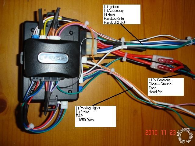
two modules on the bench prior to install.  Connect the iDatalinks' Ignition and Accessory wires to the thick Avital wires
you show in your diagram and run the thick Avital wires to the ION's ignition connector/harness.  Photo below is a Ultra
Start U1272 mated to an iDatalink bypass module w/GM4 firmware and shows the iDatalinks Pink and BLACK/ White wires
joining the corresponding thick ignition wires :

2006 saturn ion remote start -- posted image.

Soldering is fun!
keng1135 
Member - Posts: 7
Member spacespace
Joined: December 22, 2012
Location: Florida, United States
Posted: December 29, 2012 at 7:34 PM / IP Logged  
Hey thanks for the response. Yea I was going to prep everything on the table. Now I haven't ordered the idatalink because im having a little hard time understanding their product. I was told to go with the ads-al-ca but the ads-dl seem pretty much the same. and i was going to use the GM4 software. One more question, the saturn ignition wire is thin but the remote start ignition and accessory wires are thick, is that ok to solder it into the ignition wire without any problems.
Which idatalink did you get for you vehicle.
kreg357 
Platinum - Posts: 7,783
Platinum spaceThis member has made a donation to the12volt.com. Click here for more info.spaceThis member has been recognized as an authority in Electrical Theory. Click here for more info.spaceThis member has been recognized as an authority in Mobile Security and Convenience. Click here for more info.spacespace
Joined: January 30, 2009
Location: Pennsylvania, United States
Posted: December 29, 2012 at 10:26 PM / IP Logged  

The iDatalink modules are top shelf products, bullet-proof.  I use the ADS DL because it is a bit less expensive than the ADS AL CA but either module with the correct firmware will work.

Your main problem is obtaining the ADS bypass module flashed with the correct firmware.  You must find a dealer willing to flash the module for you prior to shipment.  Also get the Install Guide number at that same time so you can download and use the correct install guide.

Yes, it is perfectly fine to connect the remote starters thick ignition wires to the vehicles thin ignition wires.

Soldering is fun!
keng1135 
Member - Posts: 7
Member spacespace
Joined: December 22, 2012
Location: Florida, United States
Posted: December 29, 2012 at 11:12 PM / IP Logged  
Hey thanks for the help I just got a couple more question after observing your wiring job. Not sure if the alarm job was for a saturn ion but im sure you can answer them.
are the 12 volt constant tied into one after the fuse? is that ok to do?
I also see the trunk release output is not connected to the idatalink. is that because it didnt have one or because it wouldn't work.
Now the saturn has Positive parking lights. now can i hook them straight to the light switch without a relay and not change the polarity on the unit?
My last question hopefully. When the car is started the computer takes over and engage the starter so you can grind the starter when you turn the key and takes over cranking the car when the key is just bumped into the crank. Can I eliminate the tach wire and just use virtual tach instead
Thanks again you been a big help helping me understand this
kreg357 
Platinum - Posts: 7,783
Platinum spaceThis member has made a donation to the12volt.com. Click here for more info.spaceThis member has been recognized as an authority in Electrical Theory. Click here for more info.spaceThis member has been recognized as an authority in Mobile Security and Convenience. Click here for more info.spacespace
Joined: January 30, 2009
Location: Pennsylvania, United States
Posted: December 30, 2012 at 4:06 AM / IP Logged  

That pictured setup was used for a Colorado.  Same GM4 firmware but no need for a Trunk Release on a Pick-up.

That vehicle also uses a (-) Parking Light signal.  In the case of the ION, set the 4103 to (+) Parking Light output
and use that.

With the Colorado, I run the power directly to the battery.  Using a (-) Parking Light output, the entire remote start

assy draws less that 15 Amps.  Due to the length of the power run to the battery and the firewall passage, I fuse
down the two inputs to 10 Amps ( red fuses ), combine them onto one ( 30 Amp capable ) wire and connect that
to the battery ( for added safety, add a 20 Amp fuse to this wire within 10 inches of the battery ).

True, your vehicle has built in Anti-Grind and one touch starting.  You can try Virtual Tach if you wish ( and even

Engine Checking = OFF and a Fixed Crank Time of 1 second ) but I prefer using a true tach signal ( it's only one
more wire to run ) and Tach Mode.   In Tach Mode the 4103 provides over-rev protection and the 4103 will definitely
know when the engine is running.

Soldering is fun!
keng1135 
Member - Posts: 7
Member spacespace
Joined: December 22, 2012
Location: Florida, United States
Posted: January 06, 2013 at 11:30 PM / IP Logged  
Hi Kreg I'm almost done just got a few question. Since I try to solder the thick ignition wire from the unit to the thin wire at the ignition (wasnt working out like i want), can I solder a thinner gauge wire to the thick remote start ignition wire then solder the thinner gauge to the ignition?.
and my last question is it safe to wire the parking light wire from the unit straight to the parking light output at the switch without a relay.
im just confused on the parking light positive and negative outputs.
thanks
kreg357 
Platinum - Posts: 7,783
Platinum spaceThis member has made a donation to the12volt.com. Click here for more info.spaceThis member has been recognized as an authority in Electrical Theory. Click here for more info.spaceThis member has been recognized as an authority in Mobile Security and Convenience. Click here for more info.spacespace
Joined: January 30, 2009
Location: Pennsylvania, United States
Posted: January 07, 2013 at 4:20 AM / IP Logged  

Yes, it is OK to cut the Avitals' thick ignition output wires shorter and solder on a thinner wire to

connect to the Saturn as long as the extension wire is the same gauge or thicker than the Saturn's
wire.

Yes, you can directly connect the Avital's White Parking Light Output wire to the Saturn's (+) Parking

Light wire.  It can handle 10 Amps, just make sure you set the Avital to (+) Parking Light output
( see Programming Jumpers section in the Avitals' install guide ).

Soldering is fun!
keng1135 
Member - Posts: 7
Member spacespace
Joined: December 22, 2012
Location: Florida, United States
Posted: January 07, 2013 at 7:42 PM / IP Logged  
Hey you have been a big help I just got done installing the whole system today minus the hood pin tach and horn. virtual tach works great but if i do run into a problem I still have the tach wire. Still debating if I need the horn, like it the way it is and the hood pin well I ran out of wire loom. Everything work and tied everything to the BCM except the ignition wire.
After completing my install i just have some question about the instrument cluster lights. when its remote started i know the parking lights stays on but is it normal for the instrument cluster light to stay on as well with the headlight switch on off. Once the key is turn on and off remote start vehicle run and instrument light turns off unless I have my headlights on.
Page of 2

  Printable version Printable version Post ReplyPost New Topic
You cannot post new topics in this forum
You cannot reply to topics in this forum
You cannot delete your posts in this forum
You cannot edit your posts in this forum
You cannot create polls in this forum
You cannot vote in polls in this forum

  •  
Search the12volt.com
Follow the12volt.com Follow the12volt.com on Facebook
Tuesday, April 23, 2024 • Copyright © 1999-2024 the12volt.com, All Rights Reserved Privacy Policy & Use of Cookies
Disclaimer: *All information on this site ( the12volt.com ) is provided "as is" without any warranty of any kind, either expressed or implied, including but not limited to fitness for a particular use. Any user assumes the entire risk as to the accuracy and use of this information. Please verify all wire colors and diagrams before applying any information.

Secured by Sectigo
the12volt.com spacer
Support the12volt.com
Top
the12volt.com spacer