the12volt.com spacer
icon

turn signal to steady relay


Post ReplyPost New Topic
< Prev Topic Next Topic >
wpj74 
Member - Posts: 10
Member spacespace
Joined: January 03, 2013
Location: Ontario, Canada
Posted: April 07, 2013 at 10:59 PM / IP Logged  
Hey also your cap is connected wrong, it needs to be connected the same as the resistor.
treat it like a battery.
oldspark 
Gold - Posts: 4,913
Gold spacespace
Joined: November 03, 2008
Location: Australia
Posted: April 07, 2013 at 11:03 PM / IP Logged  
FYI - the last diagram does not have diode, hence there is no delay or hold-up time (the cap discharges thru the other bulbs).
korrupt3dazn 
Member - Posts: 11
Member spacespace
Joined: November 15, 2012
Location: Connecticut, United States
Posted: April 08, 2013 at 1:07 AM / IP Logged  
wpj74 wrote:
Hey also your cap is connected wrong, it needs to be connected the same as the resistor.
treat it like a battery.
Probably explains why it exploded lol. Thankfully I was wearing safety glasses. Never know when stuff might come flying at you. turn signal to steady relay - Page 2 -- posted image.
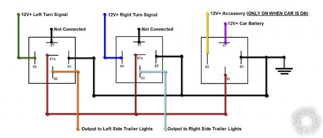
So after reviewing the link you gave me it kinda got me more confused on how he got it to work with no ground. So I drew up a new diagram. I tested it out and it works on my test bench. We will have to see once I wire it up to the car. Let me know what you guys think. As you can tell I'm a super rookie, but I feel good about this one.
turn signal to steady relay - Page 2 -- posted image.
oldspark 
Gold - Posts: 4,913
Gold spacespace
Joined: November 03, 2008
Location: Australia
Posted: April 08, 2013 at 2:09 AM / IP Logged  
Geez - I missed that the cap was connected wrong! Not that it should have blown up, but the relay would not have turned on (well, not for long if it did...).
But if you are trying to combine flashers with other lights (whether park/clearance, stop or reverse), then that 3-relay circuit won't work.
Such circuits MUST have a time function unless relays are used to connect the flasher can... IE, replace the can before the left/right switch with a link and have the switch turn on separate L & R relays that disconnect the "other" light (brake, parker, reverse) and connect the can to the bulbs - that requires a DPDT relay (or SPDT + SPST) per side (eg, like advrider - Making rear turn signals double as additional brake lights).
But also have a look at the exledusa LED flasher devices tpc-v2 or tpc-v3 ($17 & $27 a pair respectively) - I reckon they can drive a relay if the lamp current is too high. I reckon that's the best and cheapest option (unless you make & program your own ~$10 PIC etc based circuit).
Page of 2

Sorry, you can NOT post a reply.
This topic is closed.

  Printable version Printable version Post ReplyPost New Topic
You cannot post new topics in this forum
You cannot reply to topics in this forum
You cannot delete your posts in this forum
You cannot edit your posts in this forum
You cannot create polls in this forum
You cannot vote in polls in this forum

  •  
Search the12volt.com
Follow the12volt.com Follow the12volt.com on Facebook
Monday, May 6, 2024 • Copyright © 1999-2024 the12volt.com, All Rights Reserved Privacy Policy & Use of Cookies
Disclaimer: *All information on this site ( the12volt.com ) is provided "as is" without any warranty of any kind, either expressed or implied, including but not limited to fitness for a particular use. Any user assumes the entire risk as to the accuracy and use of this information. Please verify all wire colors and diagrams before applying any information.

Secured by Sectigo
the12volt.com spacer
Support the12volt.com
Top
the12volt.com spacer