the12volt.com spacer
icon

webelectric drl


Post ReplyPost New Topic
< Prev Topic Next Topic >
lurch228 
Silver - Posts: 1,338
Silver spacespace
Joined: August 08, 2012
Posted: January 05, 2013 at 8:08 PM / IP Logged  
Also you will probally need to undo the mod you did for the sidemsrker to have a constant ground for the relay too work.
oldspark 
Gold - Posts: 4,913
Gold spacespace
Joined: November 03, 2008
Location: Australia
Posted: January 06, 2013 at 3:03 AM / IP Logged  
Or you could put the LED(s) in a bridge rectifier - ie, the LED's + & - to the bridge + & - output with the "~" AC inputs to the +ve & -ve source output.
The LEDs will experience a ~1.2V drop (or ~.6V if Schottky diodes are used), but that is unlikely to have much effect.
lurch228 
Silver - Posts: 1,338
Silver spacespace
Joined: August 08, 2012
Posted: January 06, 2013 at 11:50 AM / IP Logged  
Or upon further research if you used the 194 switch back bulbs for the side marker they would be WHITE/ amber with the mod you have already done as the polarity changes. What effect it will have will depend on wether the side marker lenses are amber or clear.
daytonboi 
Member - Posts: 27
Member spacespace
Joined: August 16, 2010
Location: Ohio, United States
Posted: January 06, 2013 at 2:52 PM / IP Logged  
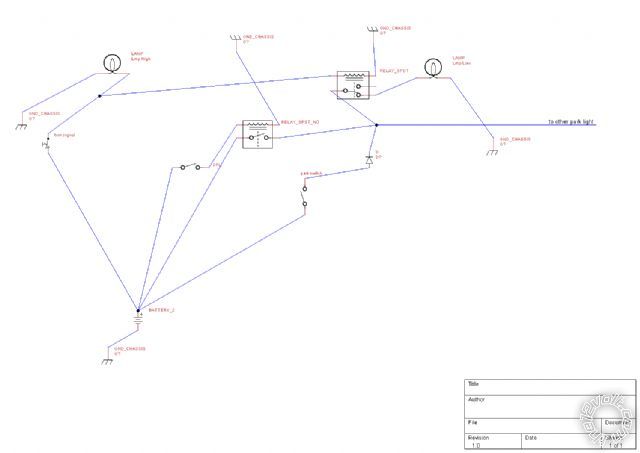
I've got a diagram, but i want to see if it is electrically sound. What we are trying to accomplish is this. He wants he wants the front parking lights on during the day. When he turns on the turn signals he wants the parking lights to go off when the turn signals come on, alternating.
webelectric drl - Page 2 - Last Post -- posted image.
2013 Chevy Impala LTZ
daytonboi 
Member - Posts: 27
Member spacespace
Joined: August 16, 2010
Location: Ohio, United States
Posted: January 06, 2013 at 2:55 PM / IP Logged  
Here is a larger version
webelectric drl - Page 2 - Last Post -- posted image.
http://tinypic.com/r/sgo38p/6
2013 Chevy Impala LTZ
daytonboi 
Member - Posts: 27
Member spacespace
Joined: August 16, 2010
Location: Ohio, United States
Posted: January 06, 2013 at 2:58 PM / IP Logged  
thanks for the help with this. Now we've moved to this DRL problem. I'm starting another thread to work on that one.
https://www.the12volt.com/installbay/forum_posts.asp~TID~133203~get~last#670748
2013 Chevy Impala LTZ
oldspark 
Gold - Posts: 4,913
Gold spacespace
Joined: November 03, 2008
Location: Australia
Posted: January 06, 2013 at 6:23 PM / IP Logged  
That will flash but out of phase with the front & rear bulbs.
I have a preference for dioding the relay coil rather than dioding the loads (co-located diodes, less current, and full voltage to the load/lamp)
Hence I'd move the park switch connection & diode to the SPDT relay coil and (therefore) also insert a diode from EACH flasher feed to the coil (remember, the flasher can is before the L-R selector switch; it's the same as sampling the flasher bulb - NOT sampling the flasher can itself).
Hence 4 diodes which can be any 1N400x type (eg, 1N4004 etc), and 2x SPDT relays (one for each side with the dioded park switch feed to both coils).
That overcomes the need for a diode rating to handle the Lmp low current, though if they are the typical 3W bulbs etc (or LEDs), that's only ~250mA and well under the 1N400x 1A rating so your 2x single diode method could be used.   
It's a pity the Low Lmps are hard grounded. If they had a wired ground, the relays would not be necessary for this type of "out of phase" flashing.
Page of 2

Sorry, you can NOT post a reply.
This topic is closed.

  Printable version Printable version Post ReplyPost New Topic
You cannot post new topics in this forum
You cannot reply to topics in this forum
You cannot delete your posts in this forum
You cannot edit your posts in this forum
You cannot create polls in this forum
You cannot vote in polls in this forum

  •  
Search the12volt.com
Follow the12volt.com Follow the12volt.com on Facebook
Saturday, May 4, 2024 • Copyright © 1999-2024 the12volt.com, All Rights Reserved Privacy Policy & Use of Cookies
Disclaimer: *All information on this site ( the12volt.com ) is provided "as is" without any warranty of any kind, either expressed or implied, including but not limited to fitness for a particular use. Any user assumes the entire risk as to the accuracy and use of this information. Please verify all wire colors and diagrams before applying any information.

Secured by Sectigo
the12volt.com spacer
Support the12volt.com
Top
the12volt.com spacer