Aw shucks, thanks! But I think you'll find I'm no different to others hereon, at least in attitude and sentiment though I do tend to
ramble more because I include extra background info (theory, or preemptive warnings etc).
They also probably express better and hence more concisely, and have detailed experience with alarms, immobilisers,
specialised relays etc whereas I tend to be more
general electrical, though batteries is one of my specialities.
I think there is a "like" link or similar though to be honest I'm ignorant of such stuff. I'm not a pro like many others and - as I recently wrote in a thread relating to another Legendary member - I was unaware of ratings other than Junior Member for quite some time LOL!
But trust me, your thanks is enough. And your extra comments just add to the buzz! (Oooo - that sounds egotistical... But look at this site - IMO it is there to educate and help.)
Now, back to technical stuff, after all this site is not a social web-chat site!

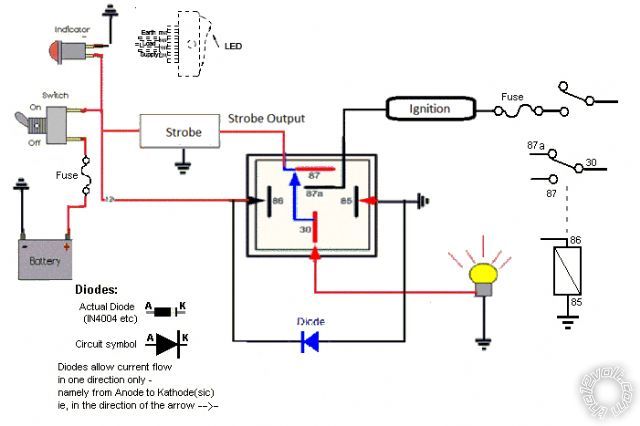
Your wiring is correct EXCEPT swap the 87 & 87a, and 87a will go to your IGN +12V.
To explain:
30 is connected to 87a when the relay is de-energised or "off".
30 is connected to 87 when the relay is energised or "on".
IE - 87a is the NC (Normally Closed) contact (see my FYI below).
Hence
normally the relay is off and IGN +12V passes thru 87a to 30 to the Eagle Eyes +12V.
When the +12V Strobe switch turns on the Strobe Module it also turns on the relay (ie, the coil's 86). Hence the relay
switches over so that the Strobe Module output to 87 connects to 30 - the Eagle Eyes (instead of IGN +12V).
So simple in hindsight isn't it? Or is that only if you draw the relay as I usually do with its coil and contact switching?
{ To explain what I mean, as I recently wrote elsewhere, ... my "circuit diagram" approach where f.ex you see the relay contacts rather than the relay body - eg, see
capacitor value for latching relay? (2nd last reply on page 1) and compare the upper
the 12volt stye wiring pic with my lower
circuit style pic - which is easier to understand behavior-wise?
}
I too should draw a diagram, and I probably will (ie, you wait; don't draw) but I also have some pressing business. (And I have yet to "draw" on my new PC.)
I'll include the protection diode I mentioned which should IMO definitely be included unless you know that the relay spike will NOT damage the module.
If I forget or take too long to post a diagram, kick me (a PM or Reply).
As to grounding, the Eagle Eyes and the Module with each have their own GND as does the relay (85).
As long as a GND is never
directly connected to +12V things should be fine. IE - all +12V connections should go to GND via a load, eg to the +12V inputs of the (grounded) eyes & module, and to 86 thru the coil to its 85 GND.
A GND is a GND whether a good nearby chassis connection for the eagle eyes, or a good (dash-) chassis connection for the switch or module, or to the battery -ve terminal, or any other good GND wire (ie, big enough to handle the required current, but that's a mere (say) 250mA for the relay, and probably only a few Amps for the module with LEDs). [Audio and other signal GNDs can be finicky so they might not be as straightforward. But this is mere switching and load stuff.]
Generally - actually probably always - I used GND wires, though for some things like headlights etc I might also have a local chassis connection.
Your switch... Oh boy!
If you only want the strobes on with IGN +12V, then it's easy. The strobe on-off switch takes its +12V from IGN +12V, probably the same (fused) circuit that is to power the LEDs as DRLs.
If you want the strobes on anytime, then a fused +12V from the battery.
You might also want ACC if wanting the strobe on whilst driving or with the key in the ACC position.
Note that ACC +12V turns off during cranking whereas IGN +12V remains on during cranking.
[Hence a optional test for you: What will the eagle eyes do when you crank the engine if the ACC powers the switch (and hence the module and LEDs) and IGN +12V powers the LEDs (as DRLs)? (If only you had my diagram, or scratched one yourself!)]
FYI - by adding diodes you can also have IGN
or ACC, ie, strobes can be on with ACC and IGN and (hence) during cranking.
You might want to use an illuminated switch so that you know the strobe is on. That means a GND wire to the switch as well (to GND its LED or lamp - and NEVER accidentally connect that GND to the wrong switch terminal!!).
And there are many switches to choose from depending on the module's current draw (
do you have that specification? - eg, 1A, 2A, 5A etc?) though using an OEM rocker or other switch is likely to easily handle that and may be easy to fit in some unused switch position/blank in the dash.
Though lengthy, I think that's covered it all except the fusing and where to tap the power from. But I'll leave that till you supply some current/load data and your powering method (strobe anytime, or IGN, or ACC).
The current may be determined various ways, but see what you can find for now.
FYI re N.O. and N.C. contacts:
The way I remember "Normally" is that's the relay's
normal state in
its box on the shelf. IE - it is not energised etc.
[ It gets confusing if a
circuit "normally" has a relay in its energised or ON state, but that is
not how we define the relay's 87a NC contact. So even if "normally" that relay is on and hence 30-87a is open, 87a is still the "Normally Closed" contact.
Unless
perhaps if that specific document or diagram or site defines otherwise...
]


 I can't see any problems. But if anyone can...
 . 23 Different flash modes for 4 lamps. Now I don't know how to connect these outputs to relay. Please help me with this.You are my angel.
 Printable version


