the12volt.com spacer
icon

Wiring SPDT Relay with Two Sources


Post ReplyPost New Topic
< Prev Topic Next Topic >
arkansas_mystic 
Member - Posts: 8
Member spacespace
Joined: January 06, 2013
Posted: January 06, 2013 at 9:06 PM / IP Logged  
Hello,
I'm looking for assistance wiring some auxiliary reverse lights on my vehicle. I have a SPDT relay that I'm using and would like to have two sources to trigger the relay. I would like the relay to activate and turn on the lights when either a) I put the vehicle into reverse or b) I flip a switch I've installed in the cab (SPST). This is the wiring diagram I tried using:
Wiring SPDT Relay with Two Sources -- posted image.
With this wiring configuration, the backup lights work when I put the vehicle in reverse but not when I flip the switch. If I disconnect the wire from the factory backup lights and connect the wire from the switch in it's place on post 85, the lights work with the switch.
Does anyone have any suggestions on making this work? I would greatly appreciate any input.
KPierson 
Platinum - Posts: 3,527
Platinum spaceThis member consistently provides reliable informationspace
Joined: April 14, 2005
Location: Ohio, United States
Posted: January 06, 2013 at 10:14 PM / IP Logged  
When the relay is not energized Pin 87A is connected to Pin 30. So, when you flip the switch on right now you are connected 12vdc from your battery, through the switch, back to 12vdc from the battery through the relay.
Unless your switch is rated with enough current to power your lights directly you shouldn't be powering the lights through the switch (after all, that is what the relay is for - high current switching).
Your best bet would be to go to RadioShack and get two 1A rectifier diodes (1n400x where x can be virtually any number). Connect the back up light through the first diode to the relay and then connect the output of your switch through the other diode to the same pin (pin 85) on the relay. Make sure on both diodes the silver band is closest to the relay. The diode will prevent one source from backfeeding in to the other source and will allow both sources to turn the relay on and off independently.
Kevin Pierson
arkansas_mystic 
Member - Posts: 8
Member spacespace
Joined: January 06, 2013
Posted: January 06, 2013 at 10:21 PM / IP Logged  
I'm new to all of this, but that was my understanding based on some research into how SPDT relays work. What I do not understand is why the wiring diagram from a light manufacturer (not the same manufacturer as the lights I installed) shows that it will work that way. I've also spoke to a guy on a vehicle specific forum I'm on and he has reverse lights wired as shown in that diagram and they work.
Regardless, I should be able to get the diodes as you suggested and get those installed. Just to be sure, you're saying connect the wire from the factory backup lights and the wire from the switch to post 85. The wire going to my auxiliary backup lights would remain connected to post 87. Is that correct? Thank you very much for your reply.
oldspark 
Gold - Posts: 4,913
Gold spacespace
Joined: November 03, 2008
Location: Australia
Posted: January 07, 2013 at 1:02 AM / IP Logged  
It sounds like it is not an SPDT relay. It may be faulty, else a dual-output SPST type.
But to add to what KP said, IMO that's a stupid setup. Why should you need a heavy duty switch and its heavy wiring and a fuse when that already exists?
I'd recommend KP's method - a light duty fused switch and wiring with two diodes (one or both which may be optional depending on the switch power source) for a common connection at the relay coil (#86 with #85 to GND).
turboled 
Member - Posts: 22
Member spacespace
Joined: December 29, 2006
Posted: January 07, 2013 at 6:20 AM / IP Logged  
It looks like the mistake in the original diagram is that the latch circuit is reversed, pin 30 should be connected to the backup light output, 87 to the power source, 87a to the switch.
turboled 
Member - Posts: 22
Member spacespace
Joined: December 29, 2006
Posted: January 07, 2013 at 6:24 AM / IP Logged  
Also, the switch in the diagram has a LED, so it nedds its own power source anyways. Maybe the intent was to use the switch to power the backup lights directly so that the LED will not turn on if there was a problem with the backup lights circuit. Just thinking...
arkansas_mystic 
Member - Posts: 8
Member spacespace
Joined: January 06, 2013
Posted: January 07, 2013 at 6:40 AM / IP Logged  
I double checked the site I ordered the relay from, it is listed as a SPDT. The diagram on the side matches what I've seen online for a SPDT relay. Also, I have two of these and have tried using both with the same result. Here's the description of the relay: 12 VDC Tyco 5-Pin Relay SPDT 20/30A
I can try switching pins 30 and 87 to see if that works. If not i can try adding the diodes (unless the diodes are a better option overall, I'll just do that first and be done with it.
gaterose 
Member - Posts: 1
Member spacespace
Joined: January 07, 2013
Location: Alabama, United States
Posted: January 07, 2013 at 7:35 AM / IP Logged  
I'm the 'guy on a vehicle forum' Ark was referring to. Just thought I'd chime in and post this, as my mind is boggled. I've wired up several sets of lights for friends with this diagram and never had any trouble.
This is a shot I took last night of my backup light relay, the angle isn't the best but you can see all the connections.
Wiring SPDT Relay with Two Sources -- posted image.
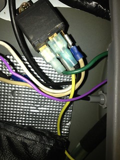
It originally started out as the relay in the diagram posted above, but I ended up changing the blue wire to yellow (needed more length) and the red wire is now off white. I have replaced the relay a few times due to getting it wet or breaking in the past. And it's just a standard configuration SPDT relay.
Btw the lights we're discussing are two 18W LED lamps, so the switch should only need to be rated at 3A+, although the lights the diagram was made for are two 55W halogens.   With the exception of the LEDs Ark has and the new one I got, in all instances that I've installed these it has been with the 55W halogens (~9A).
oldspark 
Gold - Posts: 4,913
Gold spacespace
Joined: November 03, 2008
Location: Australia
Posted: January 07, 2013 at 5:51 PM / IP Logged  
TWO CORRECTIONS to MY reply above.
Since it is a not a high power load, I withdraw my stupidity comment. (I consider 3A (36W) not unreasonable for a switch etc; and as a simple add-on to ANY relay type without the complication of diodes that wiring solution has IMO always been brilliant.)
The 2nd correction is more of a clarification:
The diagram shows an SPST relay with dual outputs (2x 87) and that will work fine as per the diagram.
But OP arkansas_mystic stated an SPDT relay in which case it has to be reversed as turboled wrote. IE - #87a from switch, #87 from +12V, #30 to LEDs/lamps.
Hence any SP relay with dual output will work - even a 4 pin with a male/female (2-way) spade connector, eg:
Wiring SPDT Relay with Two Sources -- posted image.
(Courtesy of RKS Sales and Narva)
PS - gaterose - thanks for chiming in!
And sorry to all that I missed the SPDT wiring error (thanks turboled!) else that the diagram specified SPST (which I checked from eg http://www.dodgetalk.com/forums/showpost.php?p=2265467&postcount=17 - thanks Google image search!).
KPierson 
Platinum - Posts: 3,527
Platinum spaceThis member consistently provides reliable informationspace
Joined: April 14, 2005
Location: Ohio, United States
Posted: January 07, 2013 at 6:55 PM / IP Logged  
I did not realize that the center pin is marked 87 and not 87A. The blurriness of the picture made it difficult to read. As oldspark Stated that is NOT a SPDT relay, that is an SPST relay with two contacts paralleled to the 87 pin.
As long as your switch is rated at 6A (twice the expected load) the switch would be fine. If it is rated at less then 6A I personally would use the diode method.
Kevin Pierson
Page of 3

  Printable version Printable version Post ReplyPost New Topic
You cannot post new topics in this forum
You cannot reply to topics in this forum
You cannot delete your posts in this forum
You cannot edit your posts in this forum
You cannot create polls in this forum
You cannot vote in polls in this forum

  •  
Search the12volt.com
Follow the12volt.com Follow the12volt.com on Facebook
Wednesday, April 24, 2024 • Copyright © 1999-2024 the12volt.com, All Rights Reserved Privacy Policy & Use of Cookies
Disclaimer: *All information on this site ( the12volt.com ) is provided "as is" without any warranty of any kind, either expressed or implied, including but not limited to fitness for a particular use. Any user assumes the entire risk as to the accuracy and use of this information. Please verify all wire colors and diagrams before applying any information.

Secured by Sectigo
the12volt.com spacer
Support the12volt.com
Top
the12volt.com spacer