the12volt.com spacer
icon

1995 celica remote starter


Post ReplyPost New Topic
< Prev Topic Next Topic >
doory100 
Member - Posts: 16
Member spacespace
Joined: January 12, 2013
Location: Ontario, Canada
Posted: February 04, 2013 at 8:57 PM / IP Logged  
Thanks also the black ground (-) what wire does that connect to. Also the white (-) ground when running wire connects to which wire? I have all the other wires finished. This is great help!!
McFly
kreg357 
Platinum - Posts: 7,827
Platinum spaceThis member has made a donation to the12volt.com. Click here for more info.spaceThis member has been recognized as an authority in Electrical Theory. Click here for more info.spaceThis member has been recognized as an authority in Mobile Security and Convenience. Click here for more info.spacespace
Joined: January 30, 2009
Location: Pennsylvania, United States
Posted: February 05, 2013 at 3:07 AM / IP Logged  

The R/S's Black Ground wire should have a terminal ring soldered on it.  Then it should be connected

to a paint / rust free area of the vehicles solid metal chassis.   The best locations are a factory bolt or
screw that attaches metal pieces to solid frame.  Here is a picture of a nice bolt in a convenient location
on an Impala.  The gold colored bolt in the door jam / dash side access panel.

1995 celica remote starter - Page 2 -- posted image.

For your 1995 Celica install, the White GWR wire is not used.  It is typically used to control a bypass

module, which your car does not require.

Soldering is fun!
doory100 
Member - Posts: 16
Member spacespace
Joined: January 12, 2013
Location: Ontario, Canada
Posted: February 05, 2013 at 6:05 AM / IP Logged  
Thanks for your help
McFly
doory100 
Member - Posts: 16
Member spacespace
Joined: January 12, 2013
Location: Ontario, Canada
Posted: February 14, 2013 at 10:39 PM / IP Logged  
How do I bypass my clutch?
McFly
howie ll 
Pot Metal - Posts: 16,466
Pot Metal spacespace
Joined: January 09, 2007
Location: United Kingdom
Posted: February 15, 2013 at 3:12 AM / IP Logged  
You or me Kregg?
Since I have no info I'll tell you the safe method.
Somewhere at the top of the clutch pedal support should be a switch that looks like a brake switch.
It should have two wires.
Using your DMM set to continuity, probe into each.
Is there continuity? If so you have to "open" the circuit.
More likely you only get continuity when you depress the clutch.
If the second case see diagram:- clutch_switch_2.bmp
You will need a four terminal relay (5 will do, just don't use terminal 87a) and a 1N4004 diode.
The next method will be explained by Kregg but for any further testing the VEHICLE MUST NOT BE LEFT IN GEAR.
doory100 
Member - Posts: 16
Member spacespace
Joined: January 12, 2013
Location: Ontario, Canada
Posted: February 15, 2013 at 9:05 AM / IP Logged  
What is the RS wire I use called?
McFly
howie ll 
Pot Metal - Posts: 16,466
Pot Metal spacespace
Joined: January 09, 2007
Location: United Kingdom
Posted: February 15, 2013 at 9:12 AM / IP Logged  
And the answer is...." Also the white (-) ground when running wire connects to which wire? "
Come on Kregg; post something before I end up getting banned again.
doory100 
Member - Posts: 16
Member spacespace
Joined: January 12, 2013
Location: Ontario, Canada
Posted: February 16, 2013 at 2:24 PM / IP Logged  
Yes please respond I'm not sure what he's talking about
McFly
kreg357 
Platinum - Posts: 7,827
Platinum spaceThis member has made a donation to the12volt.com. Click here for more info.spaceThis member has been recognized as an authority in Electrical Theory. Click here for more info.spaceThis member has been recognized as an authority in Mobile Security and Convenience. Click here for more info.spacespace
Joined: January 30, 2009
Location: Pennsylvania, United States
Posted: February 16, 2013 at 9:12 PM / IP Logged  

It's that British accent of his...   1995 celica remote starter - Page 2 -- posted image.

Bypassing the vehicles clutch interlock is a serious proposition.   The important things to remember are

that only a "manual transmission safe" remote start system is installed and the clutch bypass only works
during a remote start.

Depending on the vehicle, there are several types of interlocks used.   Follow Howard's instructions to

determine the type used and the wires involved.  Two points to add, if the vehicle has cruise control there
will be effectively two interlock switches at the clutch pedal.  The one for the cruise control works at the
beginning of clutch pedal movement and the starter interlock will work at the end of the pedal travel ( fully
depressed ).  Once you find the two wires involved with the starter interlock, follow Howard's diagram.  As
mentioned, the relays' control wires ( coil ) will be the (-) Ground While Running wire ( 12 Pin connector,
White wire at Pin 10 ) from the remote starter ( Pin 85 ) and the vehicles main ignition wire ( Pin 86 ).  Your
vehicle does not need a transponder bypass module, so the GWR wire is available.  The 1N4004 ( or 1N4007 )
diode should be placed across relay pins 85 to 86 with the diodes band towards pin 86.

Soldering is fun!
doory100 
Member - Posts: 16
Member spacespace
Joined: January 12, 2013
Location: Ontario, Canada
Posted: February 17, 2013 at 1:50 PM / IP Logged  
1995 celica remote starter - Page 2 -- posted image.
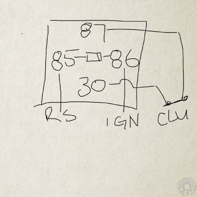
Is this correct? Diode in the middle? Or is it like howies diagram?
McFly
Page of 4

  Printable version Printable version Post ReplyPost New Topic
You cannot post new topics in this forum
You cannot reply to topics in this forum
You cannot delete your posts in this forum
You cannot edit your posts in this forum
You cannot create polls in this forum
You cannot vote in polls in this forum

  •  
Search the12volt.com
Follow the12volt.com Follow the12volt.com on Facebook
Wednesday, July 16, 2025 • Copyright © 1999-2025 the12volt.com, All Rights Reserved Privacy Policy & Use of Cookies
Disclaimer: *All information on this site ( the12volt.com ) is provided "as is" without any warranty of any kind, either expressed or implied, including but not limited to fitness for a particular use. Any user assumes the entire risk as to the accuracy and use of this information. Please verify all wire colors and diagrams before applying any information.

Secured by Sectigo
the12volt.com spacer
Support the12volt.com
Top
the12volt.com spacer