This is a DIY Pictorial for a 2011 Toyota RAV4. The 2012 model year should be the
same. This vehicle was a 4 Cylinder vehicle with the standard "G" transponder chip
ignition key (no PTS) and no Factory Alarm. The install was for a basic one-way remote
start with keyless entry.
There are several ways to implement a R/S on this vehicle. All revolve around the
bypass module. While it is possible to do a "key in the box" style install, using a
valet key is an expensive option and does increase theft risk. The next method is
a standard bypass module. There are several available but most require accessing
the IMO / IMI wires.

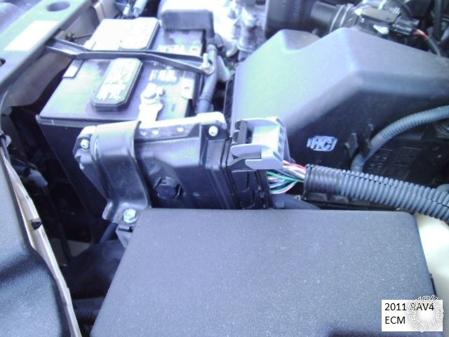
These wire can be found in at least two places - inside the vehicle,
behind the fuse box and way up high or in the engine compartment at the ECM, next to
the battery ( pictures at end of post ). The easiest and most elegant method is to use
an iDatalink bypass module ( ADS AL CA flashed with the ADS AL (DL) - TL5 firmware ).
List of parts :
Ultra Start U1272
12V Mini Relay
In-line ATC fuse holder with 10 Amp fuse
1N4007 Diode ( relay coil quench )
FLCAN bypass module ( same as ADS AL CA ) flashed with ADS AL(DL) TL5 firmware
Directed 8613 Tilt Switch
various wire, solder, heat shrink tubing, tie wraps, Scotch Super 33+ tape, etc.
Here is a picture of the R/S and bypass module bench prepped and ready for install :
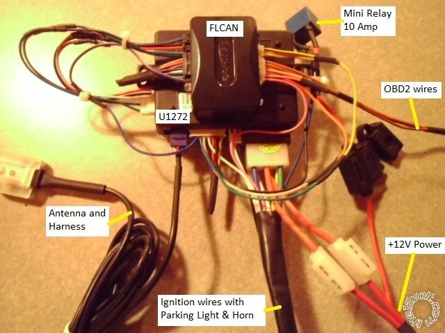
The W2W method was used between the R/S and bypass module. This U1272 unit is
only 1 way D2D compatible with the FLCAN and W2W always works better than the D2D
method. Only the necessary wires were run. The U1272 does not perform any alarm
functions, so Door and Trunk Status are not needed. This vehicle has two ignition, two
starter and one accessory wires, necessitating the extra external relay. Used for the
Ign2 or Starter2 circuit, a 10 Amp relay is sufficient. Additionally three of these ignition
wires are very thin gauge so the 30 Amp wires from the the R/S were reduced to 18 gauge
to make for an easier, neater install.
Disassembly:
Using this R/S bypass setup, only 13 wire connections to the vehicle are required. This
includes the optional Horn wire. If the vehicle has a Factory Hood Pin, the Tilt switch is
not needed as the bypass module can supply that signal to the R/S. The only items to
be removed are the lower dash panel, fuse box cover panel and the lower steering column
cover.
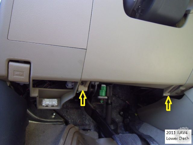
Remove the two Phillips screws indicated in the photo below and pull the lower dash panel
straight away at the top edge ( two clips, one each side).
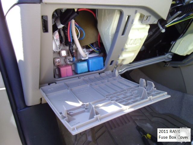
The fuse panel cover can be remove by using a non-marring trim tool and prying at the top
and right side.
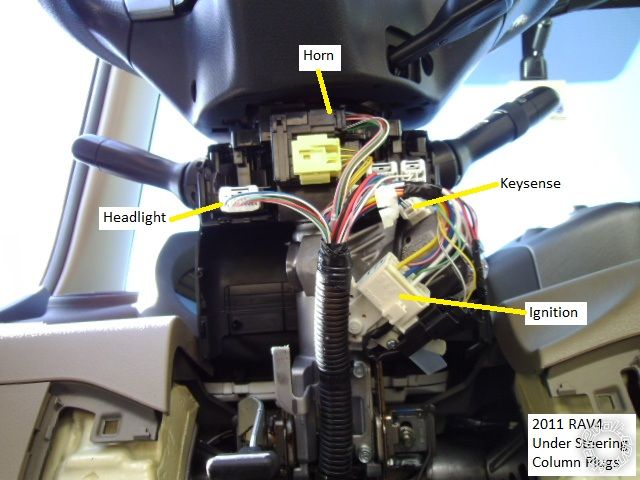
The steering column clam shell cover separates by slight pressure along the seam starting
at the rear, then use a thin blade screw driver inserted at the 3 and 9 o'clock positions on the
covers face behind the steering wheel. ( Other Toyota's used screws at these locations. )
This will expose the ignition wires.
Wiring :
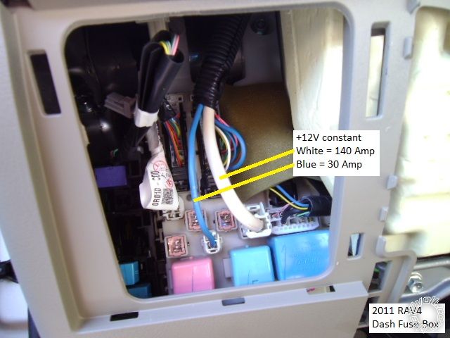
Power for the R/S system should be drawn from the thick White 140 Amp wire shown below.
However, with a R/S w/Keyless ( no alarm ) system and using the (-) Parking Lights, the Blue
wire shown just to the left is adequate and easier to make a solder connection. ( Good tip from shortcircuit161, thanks Frank! )
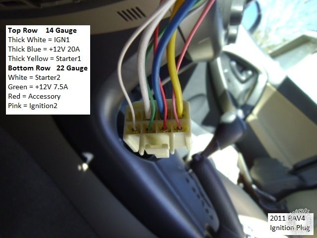
Here is a picture of the main Ignition connector with the wires marked :
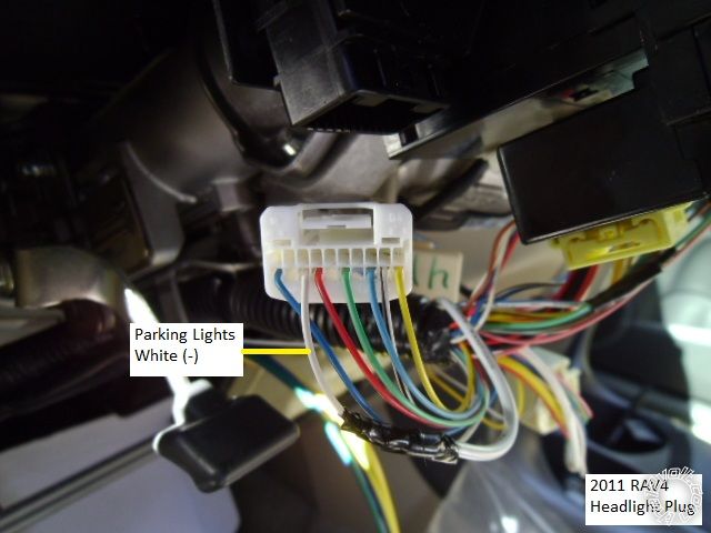
Here is a photo of the Headlight connector. If the vehicle had Auto Headlight, there would be
a Green wire to the left of the White Parking Light wire. To disable Auto Headlights during a
remote start, open this Green wire with the R/S's Ground When Running ( Status Output ) wire
and a relay.
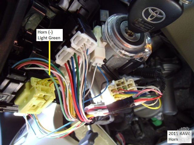
Here is a photo of the optional Horn wire :
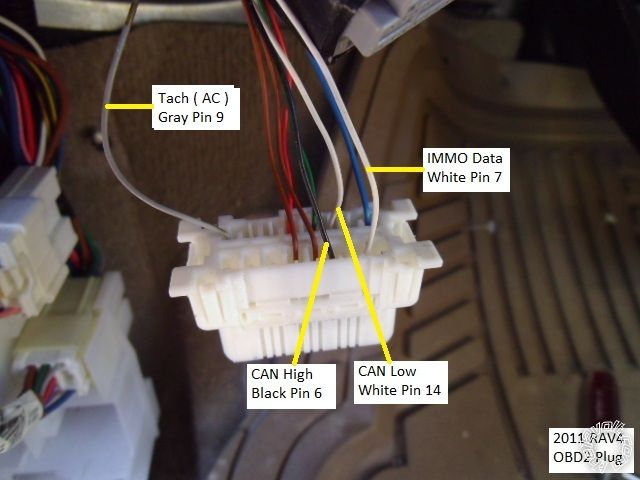
This is a shot of the OBD2 connector with the wires marked. The bypass module supplies a
Tach signal, so the OBD2 Tach wire at Pin 9 was not used for this install.
On vehicles requiring a hood pin ( no Factory Alarm ), firewall pass thru can be found at the main
harness that includes the hood release cable. This harness comes out behind the power brake
booster ( no photo ). Use a long flexible tie wrap in the hood cable hole to pass the wire(s) thru.
Notes :
There are many good locations for the Chassis Ground connection under the dash and plenty
of room to securely mount the R/S assy. The rear hatch locks and unlocks with the doors. The
iDatalink bypass module does a lot. It handles the engine immobilizer thru data and does not
require a Security Light wire. It allows the Factory FOB's to work during a remote start so a one
button R/S system is an option. The after-market R/S FOB's act the same as the Factory FOB's,
giving priority unlock and factory audio tones with lock and unlock commands.
Bonus photos for anyone not using an iDatalink bypass module... 
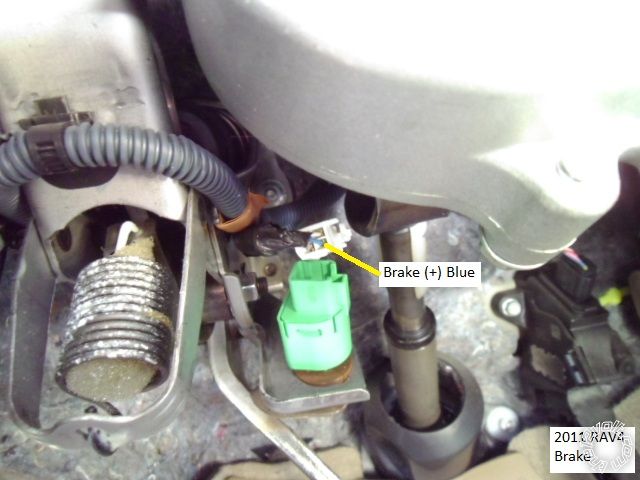
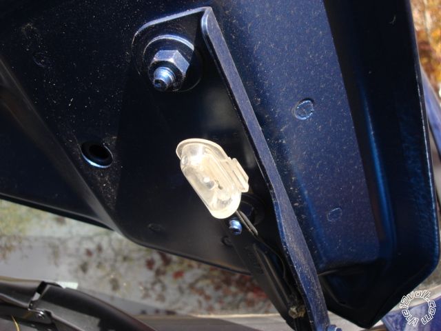
Brake wire at the pedal switch connector.
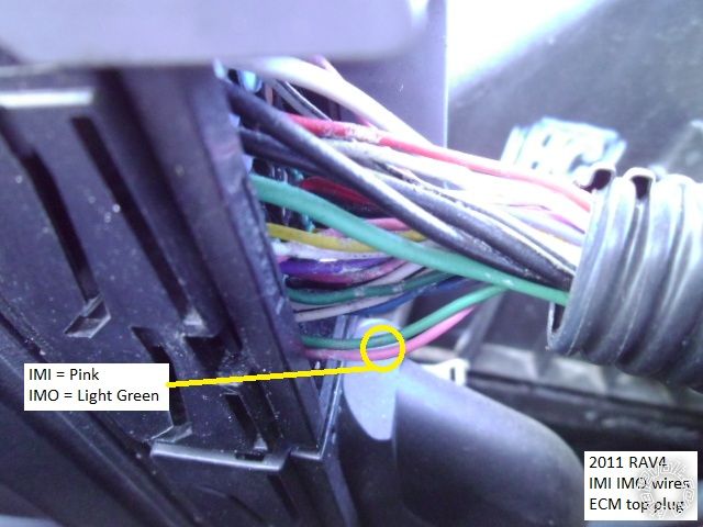
IMI / IMO wires at the ECM in the engine compartment. ( Be sure to solder and insulate /
weather-proof these connections.)
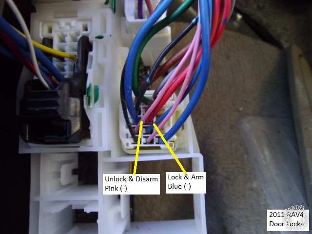
Door lock wires in the bottom connector in the drivers kick panel. These are the key
cylinder wires and do both Lock / Arm and Unlock / Disarm ( double pulse ).
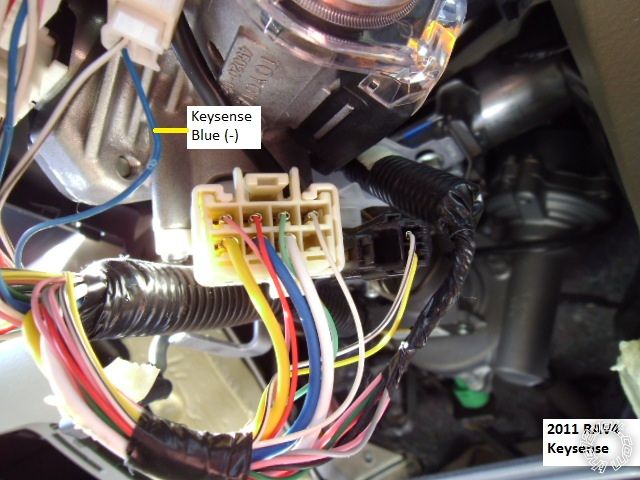
Here is a photo of the Keysense wire :
Soldering is fun!


 Topic Closed)


 The mini-relay pictured and used as IGN2 is one of those SPDT relays that has a 12V DC coil ( 36 mA ) and is capable
of a 10 Amp load across the contacts at 28V. They do not come pre-wired, or coil quenched and only cost $0.55
each in lots of 50.
The mini-relay pictured and used as IGN2 is one of those SPDT relays that has a 12V DC coil ( 36 mA ) and is capable
of a 10 Amp load across the contacts at 28V. They do not come pre-wired, or coil quenched and only cost $0.55
each in lots of 50.
 Printable version


